Near-eye display device based on polarization contact lens

A contact lens and near-eye display technology, which is applied in the field of wearable display, can solve problems such as FOV loss, overall hardware impact on user experience, and human eyes being far away, so as to improve user experience and display effect

Active Publication Date: 2018-08-14
陈超平
View PDF14 Cites 16 Cited by
  • Summary
  • Abstract
  • Description
  • Claims
  • Application Information

AI Technical Summary

Problems solved by technology

This discrete design will not only keep the human eye away from the exit pupil area, re

Method used


Image

  • Near-eye display device based on polarization contact lens
  • Near-eye display device based on polarization contact lens
  • Near-eye display device based on polarization contact lens

Examples


no. 1 example

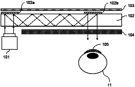
[0030] refer to figure 1 , the near-eye display device based on polarized contact lenses shown in this embodiment includes:

[0031] Micro projector 101: for projecting images;

[0032] Waveguide 102: used to fold the optical path, with at least two diffraction gratings or reflective layers on the surface or inside for the incoupling and outcoupling of light, and the expansion of the exit pupil;

[0033] Polarizer 103: used to filter light, only allowing light with a specific polarization direction to pass through;

[0034] Polarization rotator 104: used to change the polarization direction of light;

[0035] Polarized contact lens 105: used for light filtering and vision correction, only allows light of a specific polarization direction to pass through, and its diopter depends on the wearer's vision;

[0036] The near-eye display device can be a monocular display or a binocular display.

[0037] Preferably, the micro-projector 101 in this embodiment includes one or severa...

no. 2 example

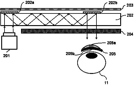
[0043] refer to figure 2 , the near-eye display device based on polarized contact lenses shown in this embodiment includes:

[0044] Micro projector 201: for projecting images;

[0045] Waveguide 202: used to fold the optical path, with at least two diffraction gratings or reflective layers on its surface or inside for the incoupling and outcoupling of light, and the expansion of the exit pupil;

[0046] Polarizer 203: used to filter light, allowing only light with a specific polarization direction to pass through;

[0047] Polarization rotator 204: used to change the polarization direction of light;

[0048] Polarized contact lens 205: used for light filtering and vision correction, only allows light of a specific polarization direction to pass through, and its diopter depends on the wearer's vision;

[0049] The near-eye display device can be a monocular display or a binocular display.

[0050] Preferably, the micro-projector 201 in this embodiment includes one or sever...

no. 3 example

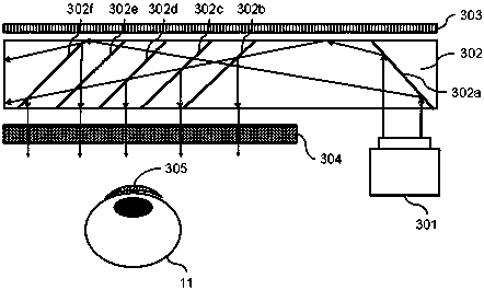
[0056] refer to image 3 , the near-eye display device based on polarized contact lenses shown in this embodiment includes:

[0057] Micro projector 301: for projecting images;

[0058] Waveguide 302: used to fold the optical path, with at least two diffraction gratings or reflective layers on the surface or inside for the incoupling and outcoupling of light, and the expansion of the exit pupil;

[0059] Polarizer 303: used to filter light, only allowing light with a specific polarization direction to pass through;

[0060] Polarization rotator 304: used to change the polarization direction of light;

[0061] Polarized contact lenses 305: used for light filtering and vision correction, only allow light in a specific polarization direction to pass through, and its diopter depends on the wearer's vision;

[0062] The near-eye display device can be a monocular display or a binocular display.

[0063] Preferably, the micro-projector 301 in this embodiment includes one or sever...


PUM


Abstract

The invention discloses a near-eye display device based on a polarization contact lens. The near-eye display device comprises a micro projector, a waveguide, a polarizer, a polarization rotator and the polarization contact lens, wherein the micro projector is used for projecting images; the waveguide is used for folding light paths, and the surface of the inside of the waveguide comprises at leasttwo diffraction gratings or reflecting layers for coupling in and coupling out of light rays and exit pupil expanding; the polarizer is used for filtering the light rays, and is only used for allowing light rays in specific polarization directions to pass through; the polarization rotator is used for changing polarization directions of the light rays; the polarization contact lens is used for light-ray filtering and vision correction, and is only used for allowing light rays in specific polarization directions to pass through, and the diopter of the polarization contact lens depends on visions of wearers; the near-eye display device can be used for monocular displaying, and can also be binocular displaying. According to the near-eye display device, the functions of the super-large field angle, actual-object shielding of a virtual object and vision correction can be achieved, and the near-eye display device is suitable for a head-mounted display device and an intelligent wearing devicesuch as intelligent lenses.

Description

technical field [0001] The invention relates to the technical field of wearable displays, in particular to a near-eye display device based on polarized contact lenses. Background technique [0002] Augmented reality (Augmented Reality, referred to as AR), is defined as a collective term for technologies used to realize the fusion and interaction between the computer-generated virtual world and the real world. Optical perspective (See-Through) near-eye display (Near-Eye Display, referred to as NED) - also known as head-mounted display - is one of the key components of augmented reality technology, and its common technical solutions are mainly Beam splitters, planar waveguides, freeform optics, retinal projection, etc. However, the current optical see-through near-eye display devices for augmented reality—represented by smart glasses—still face some urgent technical problems. For example, first, the field of view (Field of View, FOV for short) is too small, usually between 1...

Claims


Application Information

Patent Timeline
IPC IPC(8): G02B27/01
CPCG02B27/0101G02B27/0172G02B2027/0125G02B2027/0129G02B2027/0178
Inventor 陈超平米岚田张文博陆逸凡郭维谦
Owner 陈超平
Why Eureka
Try Eureka