Liquid crystal panel driving circuit
A technology for driving circuits and liquid crystal panels, used in instruments, static indicators, etc., can solve problems such as affecting user experience, abnormal output, and abnormal painting, so as to achieve the output timing without disorder, and improve reliability and user experience. Effect
- Summary
- Abstract
- Description
- Claims
- Application Information
AI Technical Summary
Problems solved by technology
Method used
Image

Examples
Embodiment Construction
[0022] The present invention will be further described below in conjunction with the accompanying drawings and embodiments.
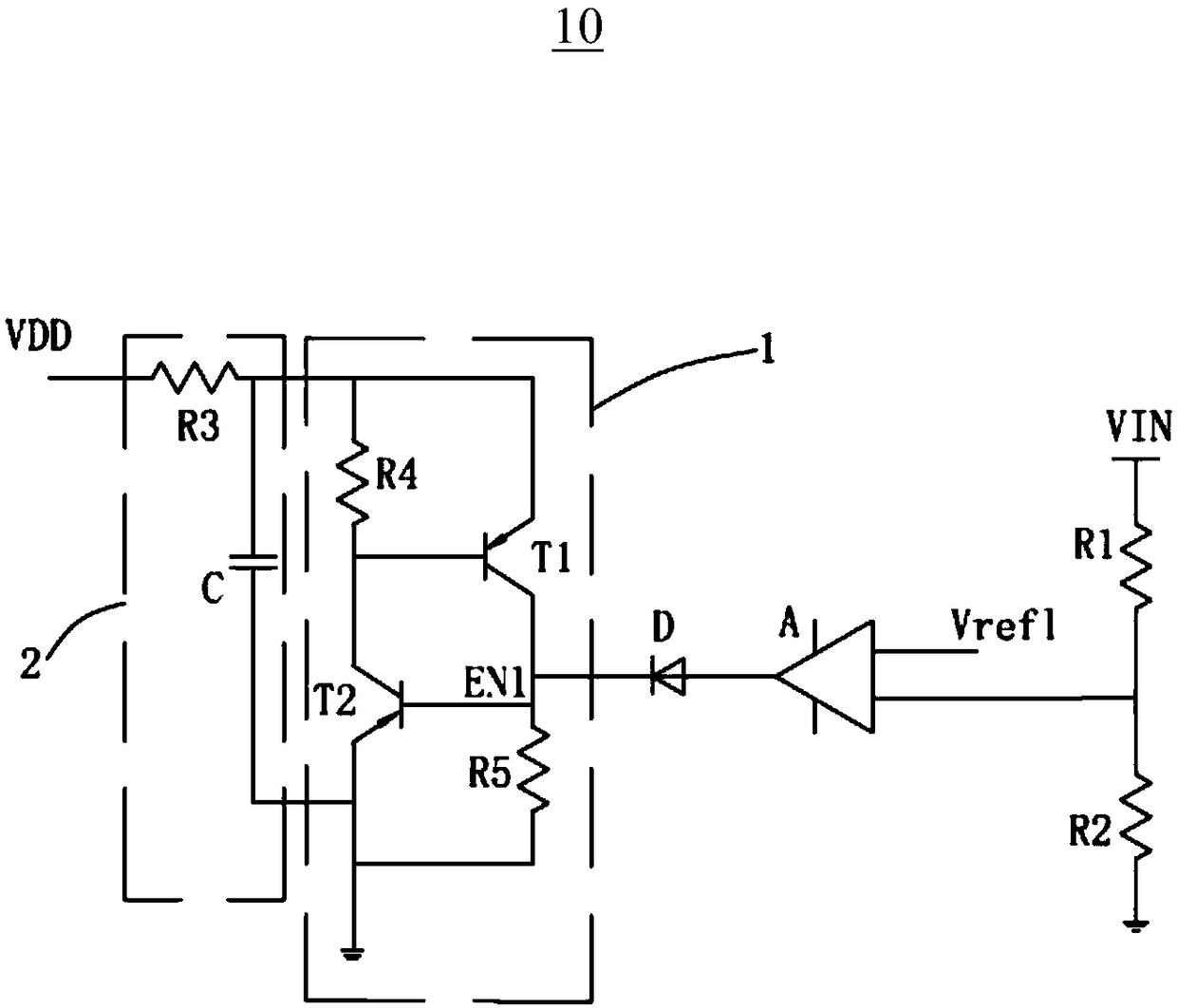
[0023] see figure 1 , is a schematic diagram of the circuit structure of the liquid crystal panel driving circuit of the present invention. The present invention provides a liquid crystal panel drive circuit, including a pulse width modulation integrated circuit 10, the pulse width modulation integrated circuit 10 includes an input terminal VIN, a first resistor R1, a second resistor R2, a comparator A, a light emitting diode D, a lock Register 1, RC circuit 2 and power supply voltage VDD.
[0024] The input terminal VIN is connected to a ground terminal through the first resistor R1 and the second resistor R2 connected in series in sequence. The positive input terminal of the comparator A is connected to the reference voltage Vref1, and the negative input terminal of the comparator A is connected between the first resistor R1 and the second resistor ...
PUM
 Abstract
Description
Claims
Application Information
 - R&D
- Intellectual Property
- Life Sciences
- Materials
- Tech Scout
- Unparalleled Data Quality
- Higher Quality Content
- 60% Fewer Hallucinations
Browse by: Latest US Patents, China's latest patents, Technical Efficacy Thesaurus, Application Domain, Technology Topic, Popular Technical Reports.
© 2025 PatSnap. All rights reserved.Legal|Privacy policy|Modern Slavery Act Transparency Statement|Sitemap|About US| Contact US: help@patsnap.com