A rapid drainage device for ICU care

A fast, drainage tube technology, applied in the direction of suction devices, balloon catheters, other medical devices, etc., can solve the problem of blockage at the end of the drainage tube, the fluid in the drainage tube is easy to flow back, and the drainage tube cannot be sealed Blockage and other problems, to achieve the effect of good anti-backflow, efficient and rapid drainage, and avoid the effect of liquid backflow

Inactive Publication Date: 2020-08-04
THE FIRST AFFILIATED HOSPITAL OF HENAN UNIV OF SCI & TECH
View PDF5 Cites 0 Cited by
  • Summary
  • Abstract
  • Description
  • Claims
  • Application Information

AI Technical Summary

Problems solved by technology

[0002] In the existing ICU nursing, it is often necessary to drain the patient's effusion during or after the operation, and the general drainage device uses negative pressure and a drainage tube to perform the drainage operation, but when draining in the body, the end of the drainage tube The problem of clogging at the inlet has never been solved well. The general solution is to increase the filter device to prevent clogging, but it cannot solve the problem fundamentally. The filter device still needs to be replaced, and even the problem that it will be completely blocked and cannot work normally will occur during use.
In the drainage of effusion, the general blockages are clots or viscous substances, etc., which are easy to cause blockage when they are sucked into the end. Therefore, it is necessary to be able to effectively deal with them to prevent blockage and ensure efficient drainage.
At the same time, the general drainage tube cannot be well sealed at the end, which brings many problems. When preventing the backflow of fluid in the drainage tube, it cannot be blocked from the inlet end, and the fluid in the drainage tube is easy to flow back.

Method used


Image

  • A rapid drainage device for ICU care
  • A rapid drainage device for ICU care
  • A rapid drainage device for ICU care

Examples


Embodiment Construction

[0029] The present invention will be further described in detail below in conjunction with the accompanying drawings and specific embodiments.

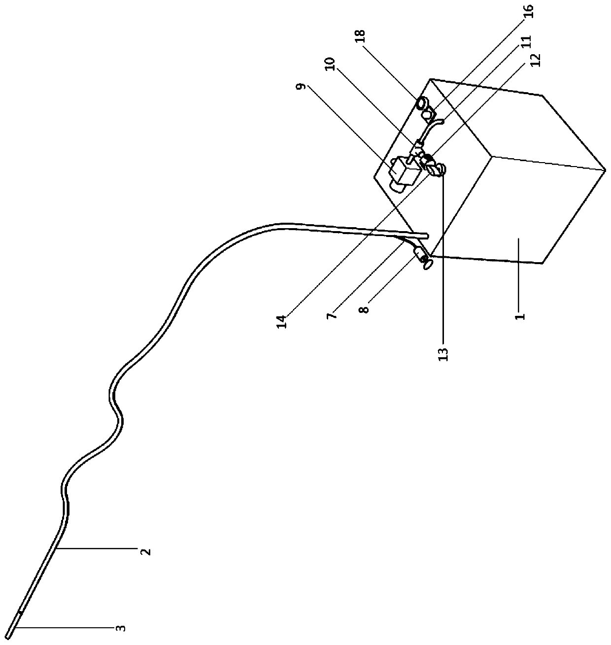
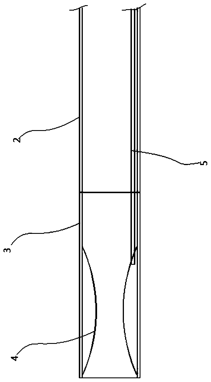
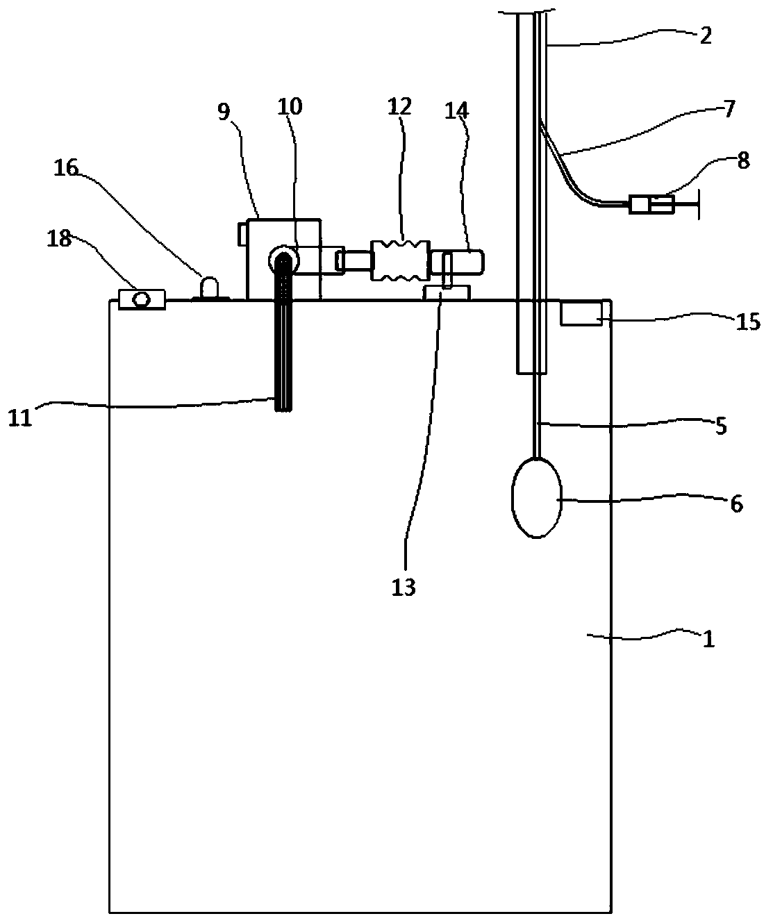
[0030] like Figure 1-6 As shown, a rapid drainage device for ICU care, comprising a collection box 1; the upper end of the collection box 1 is connected with a drainage tube 2; the drainage tube 2 is equipped with an anti-blocking device; the upper end of the collection box 1 is equipped with a pulse negative pressure device; The anti-blocking device includes a pipe head 3 communicating with the top of the drainage tube 2; the left part of the pipe head 3 is sleeved and fixedly installed with an annular elastic air bag 4; the elastic air bag 4 is connected with an air guide tube 5; , and extend into the collection box 1; in the collection box 1, the end of the airway tube 5 is connected with the control airbag 6; the middle part of the airway tube 5 is connected with a branch pipe 7; the branch pipe 7 is sealed through the middle par...


PUM


Abstract

The invention discloses a rapid drainage device for ICU nursing, and relates to the technical field of ICU critical care medicine. It includes a collection box; the upper end of the collection box is connected with a drainage tube; an anti-blocking device is installed on the drainage tube; a pulse negative pressure device is installed at the upper end of the collection box; the anti-blocking device includes a tube head connected to the top of the drainage tube; The inner left part is socketed and fixed with a ring-shaped elastic air bag; in the collection box, the end of the air guide tube is connected with a control air bag; the pulse negative pressure device includes a negative pressure pump installed on the upper end of the collection box; the suction of the negative pressure pump There is a three-way pipe connected to the end; on the front side of the sealed air bag, a drive motor is installed on the upper end of the collection box; a cam is installed on the output end of the drive motor; an air pressure sensor module is installed on the top of the collection box. The beneficial effects of the present invention are: effectively realize the anti-blocking of the inlet of the drainage end, contribute to the efficient and rapid realization of the drainage, can realize the sealing of the end conveniently, and avoid backflow.

Description

technical field [0001] The invention relates to the technical field of ICU intensive medical care. Background technique [0002] In the existing ICU nursing, it is often necessary to drain the patient's effusion during or after the operation, and the general drainage device uses negative pressure and a drainage tube to perform the drainage operation, but when draining in the body, the end of the drainage tube The problem of clogging at the inlet has never been solved well. The general solution is to prevent clogging by adding a filter device, but it cannot fundamentally solve the problem. The filter device still needs to be replaced or even completely blocked and unable to work properly during use. In effusion drainage, the general blockages are clots or viscous substances, etc., which are easy to cause blockage if they are sucked into the end. Therefore, it is necessary to be able to effectively treat them to prevent blockage and ensure efficient drainage. Simultaneously, ...

Claims


Application Information

Patent Timeline
Patent Type & Authority Patents(China)
IPC IPC(8): A61M1/00A61M25/10
CPCA61M25/0074A61M25/10A61M2205/3331A61M1/742A61M1/75A61M1/78A61M1/85A61M1/88A61M1/90
Inventor 张小飞王莹聂明斐
Owner THE FIRST AFFILIATED HOSPITAL OF HENAN UNIV OF SCI & TECH
Why Eureka
Try Eureka