Numerical control machine tool facilitating machined workpiece clamping
A technology for CNC machine tools and processing parts, which is applied to metal processing machinery parts, metal processing equipment, clamping, etc., can solve the problems of processing parts stuck, time wasting, inconvenient removal, etc., to save time, use conveniently, improve The effect of the clamping effect
- Summary
- Abstract
- Description
- Claims
- Application Information
AI Technical Summary
Problems solved by technology
Method used
Image

Examples
Embodiment Construction
[0019] The following will clearly and completely describe the technical solutions in the embodiments of the present invention with reference to the accompanying drawings in the embodiments of the present invention. Obviously, the described embodiments are only some, not all, embodiments of the present invention.
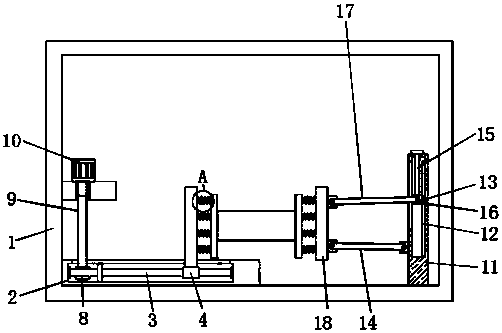
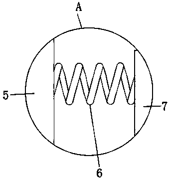
[0020] refer to Figure 1-2 , a kind of numerically controlled machine tool that is convenient for clamping workpieces, comprising a machine tool body 1, a mounting plate 2 is fixed on one side of the inner bottom wall of the machine tool body 1, a groove is arranged at the middle position of the mounting plate 2, and the inner walls on both sides of the groove are A threaded sleeve 3 is installed in rotation, and one end of the threaded sleeve 3 is threaded with a connection block 4, and the top of the connection block 4 is provided with a first fixing plate 5, and the end of the threaded sleeve 3 away from the connection block 4 is threaded with a worm wheel 8, and ...
PUM
 Abstract
Description
Claims
Application Information
 - Generate Ideas
- Intellectual Property
- Life Sciences
- Materials
- Tech Scout
- Unparalleled Data Quality
- Higher Quality Content
- 60% Fewer Hallucinations
Browse by: Latest US Patents, China's latest patents, Technical Efficacy Thesaurus, Application Domain, Technology Topic, Popular Technical Reports.
© 2025 PatSnap. All rights reserved.Legal|Privacy policy|Modern Slavery Act Transparency Statement|Sitemap|About US| Contact US: help@patsnap.com