Bearing pedestal deburring device

A bearing seat and deburring technology, which is used in grinding drive devices, grinding/polishing safety devices, grinding machines, etc., can solve the problems of low operation efficiency, complex surface shape, monotonous operation action, etc., and achieves simple structure and convenient operation. , the effect of improving work efficiency

Inactive Publication Date: 2018-08-17
响水星火传动件有限公司
View PDF0 Cites 2 Cited by
  • Summary
  • Abstract
  • Description
  • Claims
  • Application Information

AI Technical Summary

Problems solved by technology

In addition, the process of removing chips and applying anti-rust oil on the bearing seat is labor-intensive and the operation is monotonous. The factory urgently needs a method to improve
Construction machinery parts are mostly processed by heavy cutting, and there are often burrs around the junction between the machined surface and cast iron; for parts with oil passage holes, the surface shape is complex, and it is time-consuming and laborious to use manual pneumatic grinding wheels to remove the burrs around the machined surface, which often causes damage to the machined surface. the scratch
In the case of heavy product output, the operator's work is light and the work efficiency is low

Method used


Image

  • Bearing pedestal deburring device
  • Bearing pedestal deburring device

Examples


Embodiment Construction

[0018] The following will clearly and completely describe the technical solutions in the embodiments of the present invention with reference to the accompanying drawings in the embodiments of the present invention. Obviously, the described embodiments are only some, not all, embodiments of the present invention.

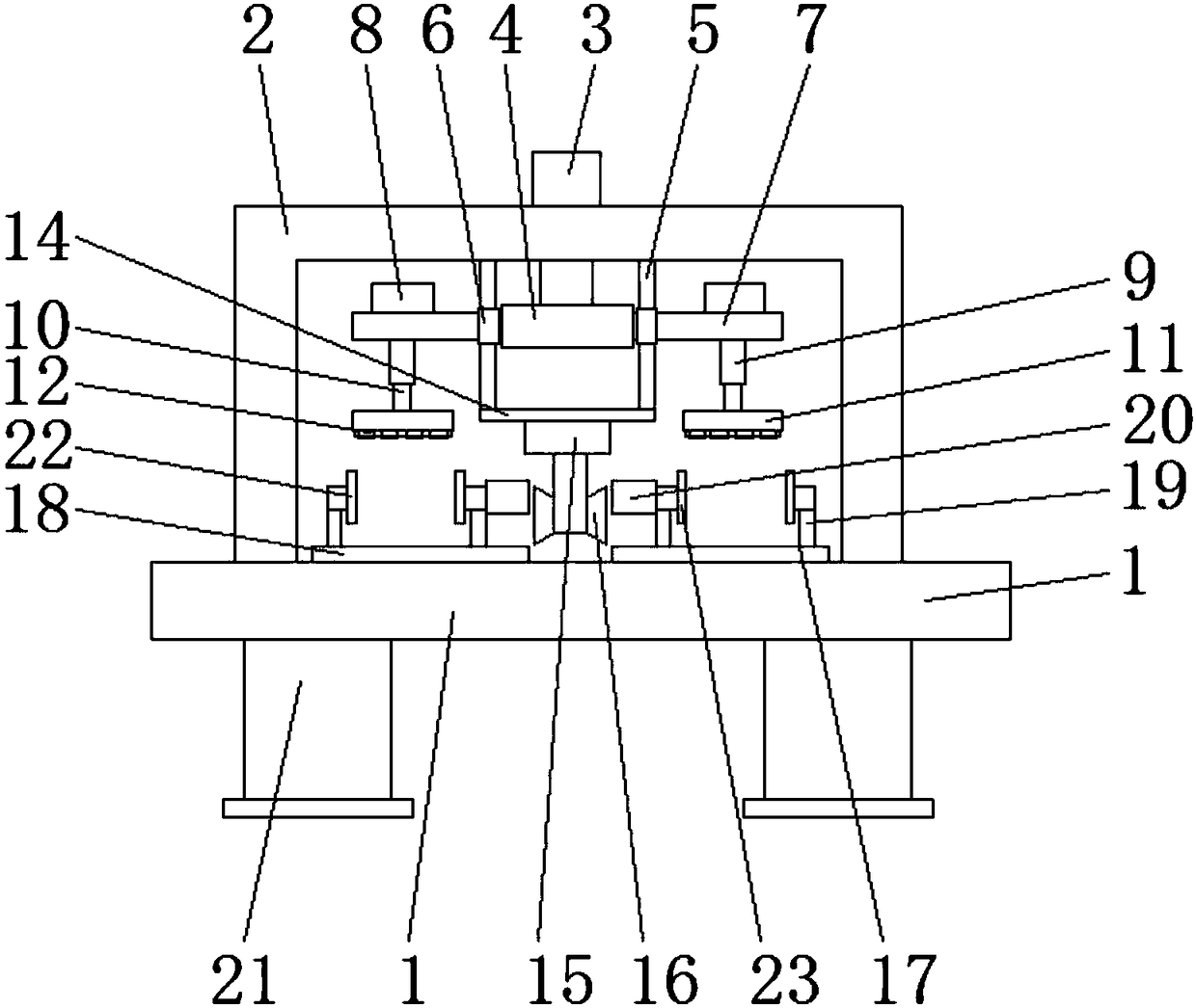
[0019] refer to Figure 1-2 , a bearing seat deburring device, including a workbench 1, a frame 2 is arranged on the workbench 1, a cylinder 3 is installed in the center of the top of the frame 2, and the output end of the cylinder 3 runs through the top of the frame 2 and is fixedly connected with a guide plate 4. Both sides of the guide plate 4 are symmetrically provided with guide rails 5, the two ends of the guide plate 4 are fixedly connected with the sliding sleeve 6 matching the guide rail 5, and the side of the sliding sleeve 6 away from the guide plate 5 is fixedly connected with the installation plate 7, and the installation The plate 7 is provided with a d...


PUM


Abstract

The invention discloses a bearing pedestal deburring device. The bearing pedestal deburring device comprises a workbench. The workbench is provided with a rack. An air cylinder is installed in the middle of the top of the rack. The output end of the air cylinder penetrates the top of the rack to be fixedly connected with a guide plate. The two sides of the guide plate are symmetrically provided with guide rails. The two ends of the guide plate are fixedly connected with sliding sleeves matched with the guide rails. The sides, far away from the guide plate, of the sliding sleeves are fixedly connected with installation plates. The installation plates are provided with drive motors. Output shafts of the drive motors penetrate the corresponding installation plates to be connected with rotating shafts through couplers. The lower ends of the rotating shafts are fixedly connected with brush plates. The bottoms of the brush plates are provided with brushes, and the outer sides of the brushesare covered with protective gauze covers. A hanger plate is arranged between the bottoms of the two guide rails. The bottom of the hanger plate is provided with a draught fan. The bottom of the draught fan is provided with two opposite air outlets. The parts, under the brush plates, of the workbench are provided with bearing pedestal positioning mechanisms. The bearing pedestal deburring device isgood in deburring effect, the labor intensity of an operator is lowered, and the working efficiency is improved.

Description

technical field [0001] The invention relates to the technical field of bearing seat cleaning, in particular to a bearing seat deburring device. Background technique [0002] At present, the bearing seat plays the role of supporting the half shaft in the transmission of the bulldozer, and the oil passage hole on the bearing seat plays the role of the oil passage at the same time. In the damage of many bulldozer parts, it is found that there are chips in the oil passage. The investigation found that the process of deburring and cleaning the chips of the bearing housing and applying anti-rust oil is the last process before equipment. The degree of cleanliness has a certain impact on avoiding chips in the oil passage. In addition, the process of removing chips and applying anti-rust oil on the bearing seat is labor-intensive and the operation is monotonous. The factory urgently needs an improved method. Construction machinery parts are mostly processed by heavy cutting, and the...

Claims


Application Information

Patent Timeline
Patent Type & Authority Applications(China)
IPC IPC(8): B24B9/04B24B41/06B24B41/02B24B47/12B24B55/06B24B47/00
CPCB24B9/04B24B41/02B24B41/06B24B47/00B24B47/12B24B55/06
Inventor 于宇
Owner 响水星火传动件有限公司
Why Eureka
Try Eureka