
Deviation correcting structure and method of horizontal locking broken column

A technology of horizontal locking and fracture, which is applied in infrastructure engineering, building construction, building maintenance, etc., can solve problems such as broken column correction, existing building safety risks, and house dumping, and achieve the effect of avoiding dumping.

Active Publication Date: 2018-08-17
广东中青建筑科技有限公司
View PDF4 Cites 2 Cited by
  • Summary
  • Abstract
  • Description
  • Claims
  • Application Information

AI Technical Summary

Problems solved by technology

However, to rectify the deflection of a broken column, the column must be disconnected first, and then jacked up for adjustment. During the process of breaking the column, there is a risk of building safety. At the same time, there is also a risk of collapse of the house caused by a sudden horizontal load (such as an earthquake) after the broken column

Method used


Image

  • Deviation correcting structure and method of horizontal locking broken column
  • Deviation correcting structure and method of horizontal locking broken column
  • Deviation correcting structure and method of horizontal locking broken column

Examples


Embodiment 1

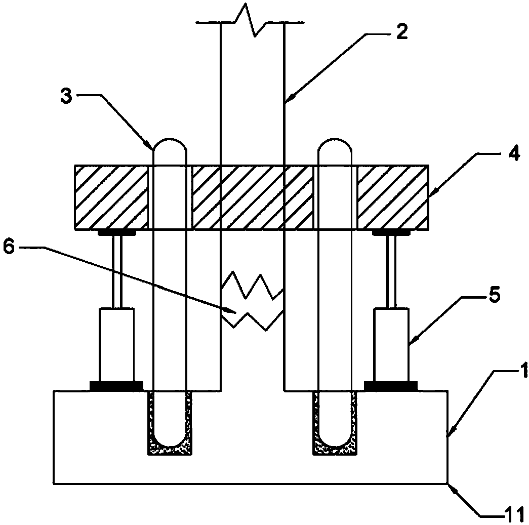
[0032] like figure 1 As shown, a deviation correction structure for horizontally locking a broken column includes a building foundation 1 and a load-bearing column 2, the load-bearing column 2 is provided with a fracture 6, and the periphery of the load-bearing column 2 is fixedly connected with a column-holding tray 4, so The fracture 6 is located between the column-holding tray 4 and the building foundation 1, and at least two support piles 3 are arranged around the load-bearing column 2, and one end of the support pile 3 is embedded in the building foundation 1. The other end of the support pile 3 is pierced through the pillar-holding tray 4 , and a jacking device 5 for jacking up the pillar-holding tray 4 is provided below the pillar-holding tray 4 .

[0033] The load-bearing column 2 is the load-bearing column 2 of the original building. In this embodiment, the jacking device 5 is a jack. In other embodiments, other jacking devices 5 can be selected. One end of the suppo...

Embodiment 2

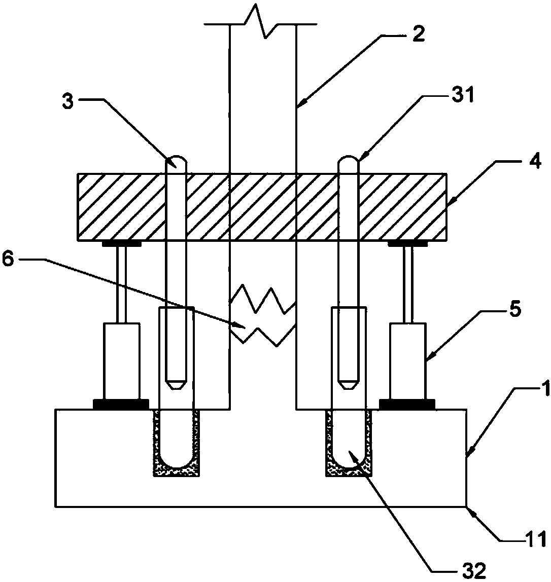
[0038] like figure 2 As shown, the difference between this embodiment and Embodiment 1 is that each of the support piles 3 includes a lower support pile 32 embedded in the building foundation 1 and an upper support pile 31 pierced through the pillar-holding tray 4 , the upper supporting pile 31 is slidably sleeved in the lower supporting pile 32 , and the upper supporting pile 31 can only move away from the lower supporting pile 32 .

[0039] The lower support pile 32 is buried in the building foundation 1, the upper support pile 31 is fixed with the support tray 4, and the upper support pile 31 is sleeved in the lower support pile 32, and can only move upward. Lifting device 5 jacks up and holds the supporting pallet 4, and the upper part of the load-bearing column 2 and the upper support pile 31 also move upwards along with the supporting pallet 4, and because the upper supporting pile 31 can only move upwards in the lower supporting pile 32. Moving downwards, in fact, the...

Embodiment 3

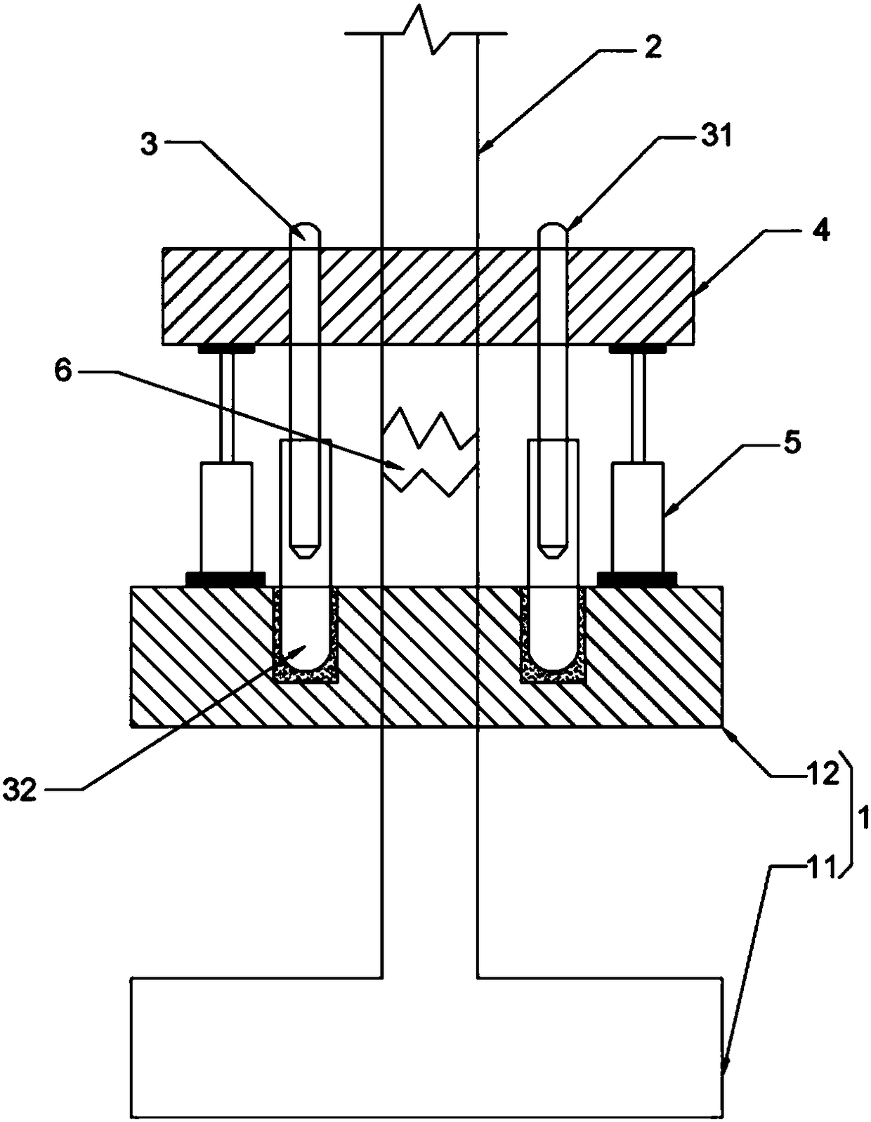
[0043] like image 3 As shown, the difference between this embodiment and implementation 1-2 is: when the original foundation 11 is deeply buried, the building foundation 1 is a new foundation 12, and the new foundation 12 is set at a place where the ground bearing capacity is sufficient, and the next The support pile 32 is embedded in the newly added foundation 12, and the disconnection is opened between the newly added foundation 12 and the pallet on the pillar.


PUM


Abstract

The invention relates to the technical field of buildings, in particular to a deviation correcting structure and method of a horizontal locking broken column. The deviation correcting structure of thehorizontal locking broken column comprises a building foundation and a bearing column, and is characterized in that the bearing column is provided with a fracture, a column holding bearing tray is fixedly connected to the periphery of the bearing column, the fracture is located between the column holding bearing tray and the building foundation, at least two supporting piles are arranged on the periphery of the bearing column, one end of each supporting pile is embedded into the building foundation, the other end of each supporting pile penetrates through the column holding bearing tray, anda jacking device used for jacking the column holding bearing tray is further arranged under the column holding bearing tray. The structure is simple; in the jacking process, the risk of toppling caused by the influence of a horizontal load is avoided.

Description

technical field [0001] The invention relates to the field of construction technology, in particular to a deviation correction structure for horizontally locking broken columns and a deviation correction method for horizontally locking broken columns. Background technique [0002] The traditional deviation correction of building foundations either adopts the lifting of broken columns to adjust the deviation, or uses the forced landing of the foundation soil to correct the deviation. However, to rectify the deflection of a broken column, the column must be disconnected first, and then jacked up for adjustment. During the process of breaking the column, there is a risk of building safety. At the same time, there is also a risk of collapse of the house caused by a sudden horizontal load (such as an earthquake) after the broken column . Contents of the invention [0003] In order to overcome the shortcomings and deficiencies in the prior art, the object of the present inventio...

Claims


Application Information

Patent Timeline
Patent Type & Authority Applications(China)
IPC IPC(8): E04G23/02E02D35/00
CPCE02D35/00E04G23/0218
Inventor 杨孝张艳红王胜忠杨敬
Owner 广东中青建筑科技有限公司
Learn More