Solar energy and finned pulsating heat pipe phase change energy storage coupling system

A phase change energy storage, pulsating heat pipe technology, applied in solar heating systems, solar thermal energy, solar collectors, etc., can solve the problems of large thermal inertia of heat dissipation equipment, poor thermal comfort, and uneven indoor heating, and achieve indoor temperature. Uniform distribution, improved thermal inertia, uniform indoor temperature

CN108413468AInactive Publication Date: 2018-08-17NORTHEAST GASOLINEEUM UNIV
4 Cites 5 Cited by

Patent Information

Authority / Receiving Office
CN · China
Patent Type
Applications(China)
Current Assignee / Owner
Publication Date
2018-08-17
Estimated Expiration
Not applicable · inactive patent

Smart Images

  • Figure 1
    Figure 1
  • Figure 2
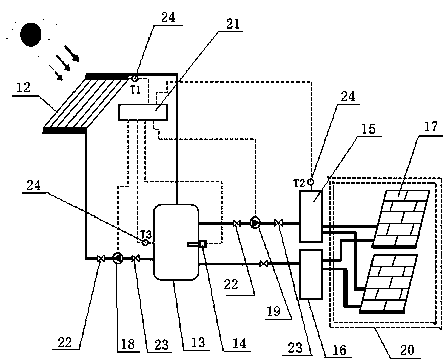
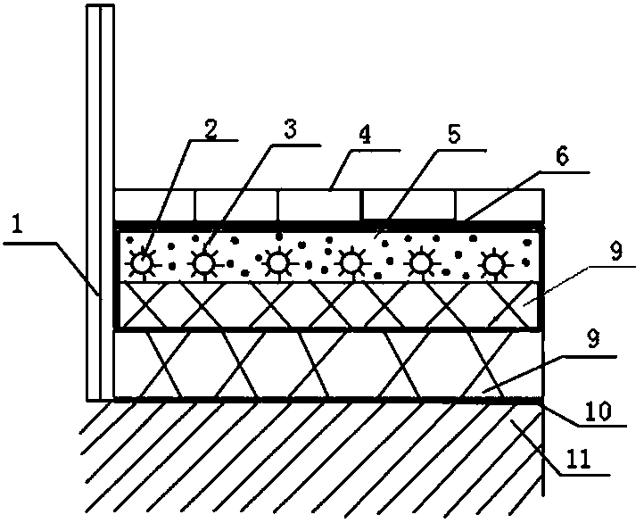
    Figure 2
  • Figure 3
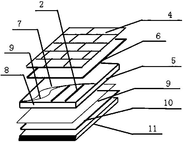
    Figure 3
Patent Text Reader

Abstract

The invention relates to a solar energy and finned pulsating heat pipe phase change energy storage coupling system which comprises a vacuum superconducting solar heat collector, a heat storage water tank and multiple groups of pulsating heat pipe phase change energy storage floors; the vacuum superconducting solar heat collector, the heat storage water tank and a water diversion tank are sequentially connected with one another through a water inlet pipeline; a solar circulation pump is arranged on the water inlet pipeline between the vacuum superconducting solar heat collector and the heat storage water tank; a floor circulation pump is arranged on the water inlet pipeline between the heat storage water tank and the water diversion tank; the water diversion tank is connected with water inlets of multiple groups of the pulsating heat pipe phase change energy storage floors; water outlets of multiple groups of the pulsating heat pipe phase change energy storage floors are connected to awater collection tank; the water collection tank, the heat storage water tank and the vacuum superconducting solar heat collector are sequentially connected with one another through a water return pipe; the vacuum superconducting solar heat collector, the heat storage water tank and the water diversion tank are provided with temperature sensors respectively; and each temperature sensor is connected with a controller. The solar energy and finned pulsating heat pipe phase change energy storage coupling system provided by the invention improves the thermal inertia of the traditional heating terminal device and the solar heat collection efficiency.
Need to check novelty before this filing date? Find Prior Art

Description

technical field

[0001] The invention relates to a heating device, in particular to a solar energy and finned pulsating heat pipe phase change energy storage coupling system. Background technique

[0002] Cold regions are rich in solar energy resources, and the solar irradiance is strong, and the end of the solar heating system mostly uses traditional radiators (radiators) to dissipate heat and heat indoors. Traditional radiator (radiator) heating systems require high water supply temperature, resulting in low solar heating heat collection efficiency; solar heating systems are constrained by the weather, and cannot continue to provide heating to indoor rooms at night or on rainy days, failing to meet the heating demand; and Traditional radiators (radiators) have large thermal inertia and cannot make the indoor temperature reach thermal comfort in time. Contents of the invention

[0003] The purpose of the present invention is to provide a solar energy and finned pulsating ...

Examples

Embodiment Construction

[0017] Below in conjunction with accompanying drawing, the present invention will be further described:

[0018] Such as figure 1 As shown, this solar energy and fin type pulsating heat pipe phase change energy storage coupling system includes a vacuum superconducting solar collector 12, a hot water storage tank 13, a water distribution tank 15, multiple groups of pulsating heat pipe phase change energy storage floors 17, a collector Water tank 16, controller 21, vacuum superconducting solar heat collector 12, hot water storage tank 13, water distribution tank 15 are connected successively by water inlet pipeline, and the inlet between vacuum superconducting solar heat collector 12 and hot water storage tank 13 A solar circulation pump 18 is installed on the water pipeline, a ball valve 22 is installed at the inlet of the solar circulation pump 18, a check valve 23 is installed at the outlet of the solar circulation pump 18, and a floor circulation is installed on the water in...