
Heat radiating fin

A technology of heat sinks and peaks, applied in the field of corrugated heat sinks, can solve the problems of rising manufacturing costs, difficulty in processing shutters, and increasing surface area, so as to eliminate heat stagnation, increase surface area, and improve heat dissipation capacity. Effect

Active Publication Date: 2018-08-17
JAPAN
View PDF12 Cites 0 Cited by
  • Summary
  • Abstract
  • Description
  • Claims
  • Application Information

AI Technical Summary

Problems solved by technology

Therefore, there is a limit to increasing the number of peaks and valleys by reducing the distance (pitch) and increasing the surface area.
[0004] Furthermore, such a louver is difficult to process, and the louver needs to be formed before bending into continuous peaks and valleys. However, the bending process of such a louvered plate is restricted in the bending method, and the manufacturing cost also increases.

Method used


Image

  • Heat radiating fin
  • Heat radiating fin
  • Heat radiating fin

Examples


Embodiment Construction

[0048] Next, embodiments of the present invention will be described in detail based on the drawings.

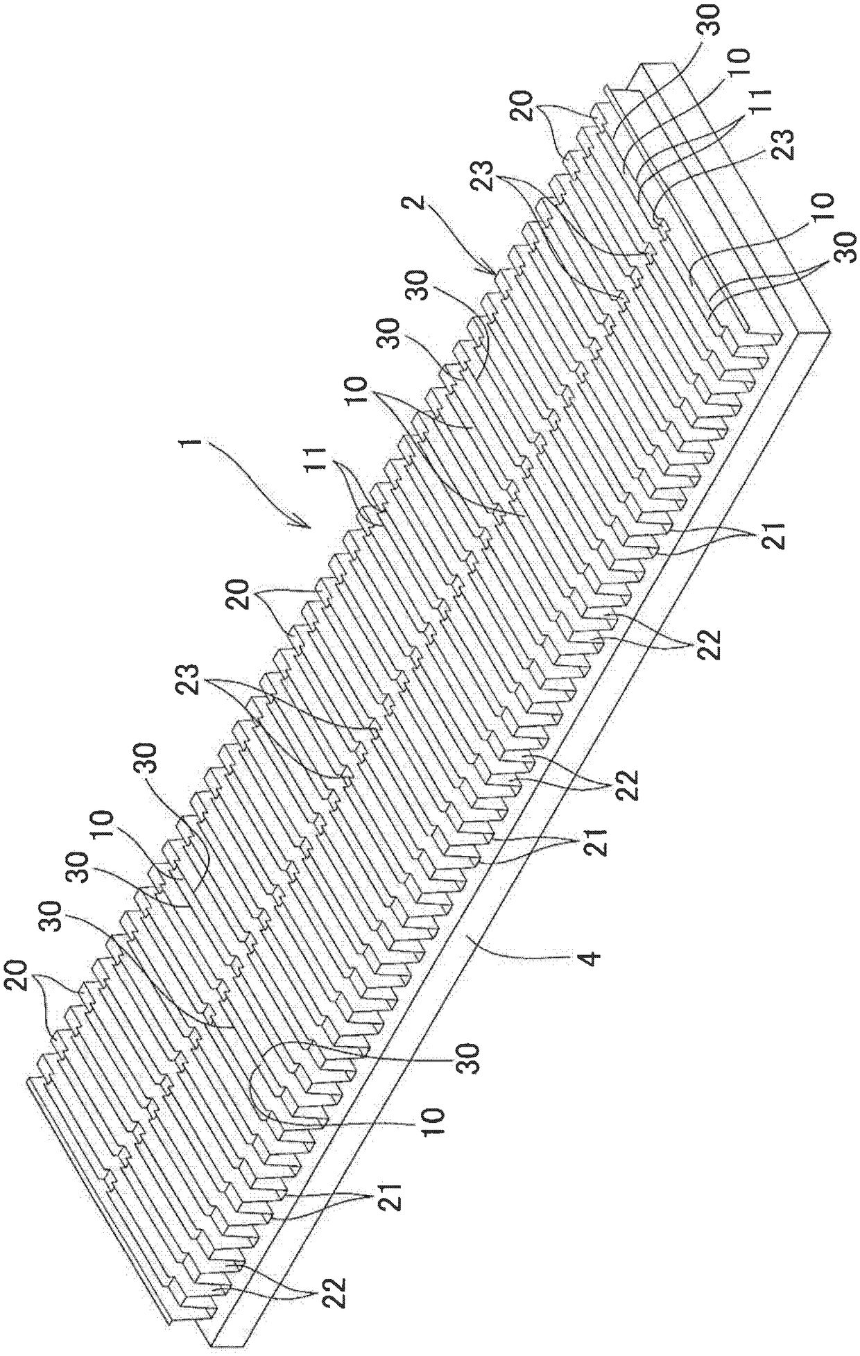
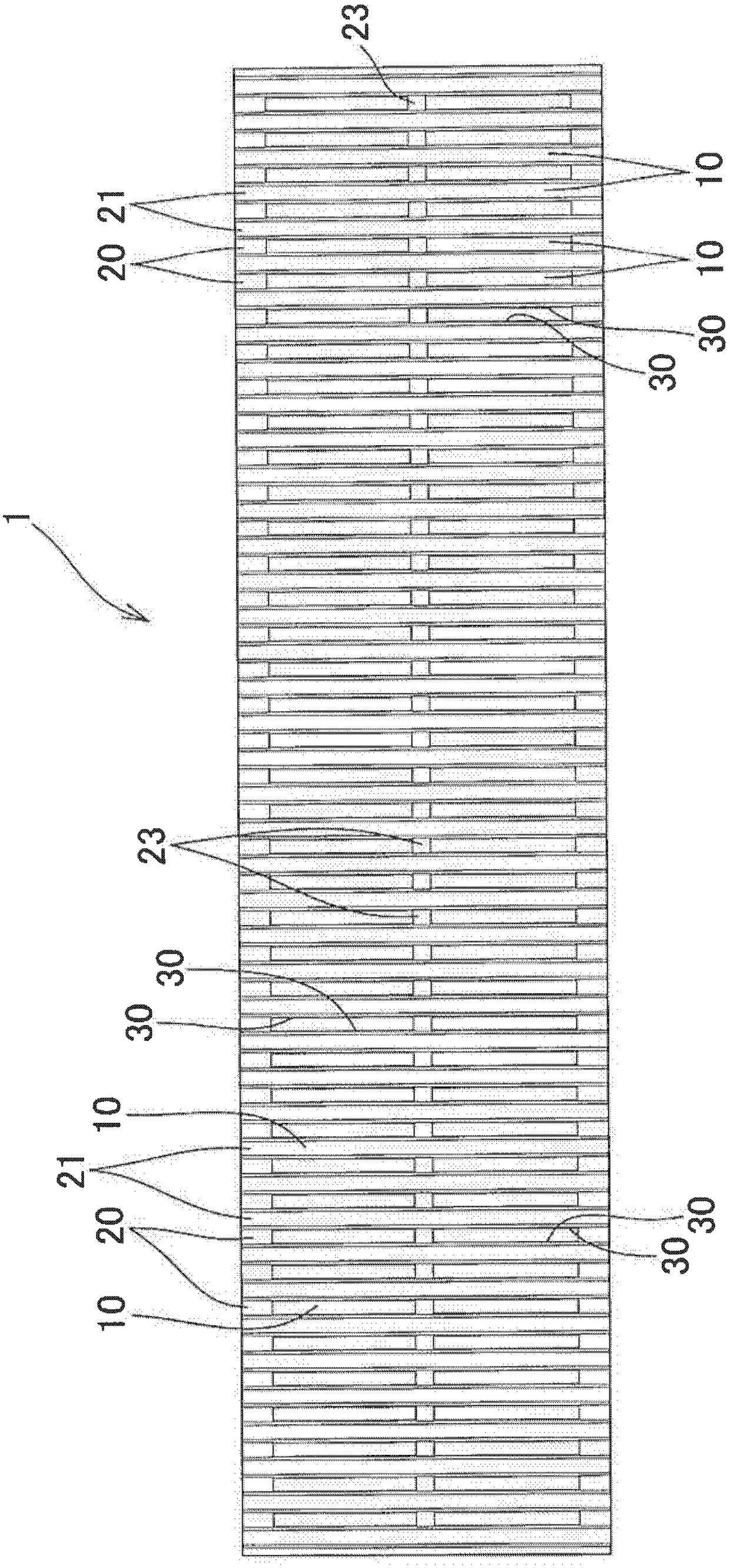
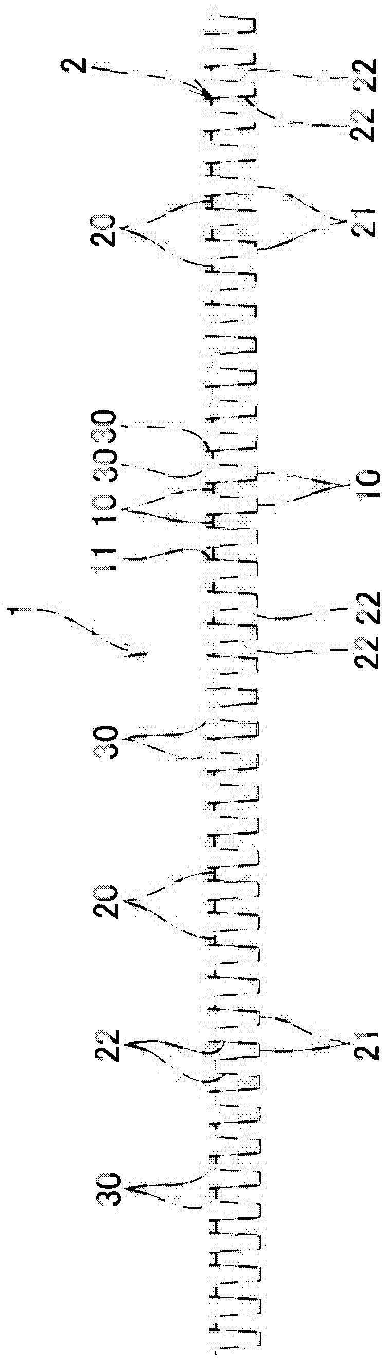
[0049] Such as Figure 1 to Figure 5 As shown, the heat sink 1 of the present invention is provided with through grooves 10 extending in the column direction for passing fluid on the above-mentioned peaks 20 of the metal plate 2 in which a plurality of column-shaped peaks 20 and valleys 21 are alternately formed. , and the opening edge portion 11 of the through groove 10 is provided with a rising piece 30 rising toward the convex side of the peak portion 20, and is installed so that the convex side surface of the valley portion 21 faces the object 4 to be cooled.

[0050] In this embodiment, an example is shown in which the heat sink 1 is attached and used in a state where the convex surface side of the valley portion 21 is directly in contact with the object 4 to be cooled, but it is not limited thereto. For example, although not shown, it may also be configured as A base m...


PUM


Abstract

The invention provides a heat radiating fin. The heat radiating fin has a through trough (10) which extends in a row direction at a peak part (20). Furthermore the opening edge parts (11) of the through trough (10) are provided with vertical projecting plates (30) which project to the convex side of the peak part (20). The vertical projecting plates (30) are arranged at a pair of opening edge parts (11,11) which extend in the row direction. Each vertical projecting plate (30) is an elongated plate which extends in a manner of transversal the approximate total length of each opening edge part (11). Therefore, in the corrugated heat radiating fin, even on the condition that the heat radiation fin is used as a natural convection type heat radiating fin, heat non-circulation can be prevented for sustaining high heat radiating performance. Furthermore, the interval (distance) between the middle wall parts can be reduced for increasing the number of peaks and volleys and increasing the surface area. Furthermore high-efficiency and low-cost manufacture can be realized.

Description

technical field [0001] The present invention relates to a corrugated heat sink that is formed of a metal plate in which a plurality of rows of peaks and valleys are alternately formed, and is attached so that the surface on the convex side of the valleys faces an object to be cooled. Background technique [0002] Currently, such corrugated fins have the problem that the heat fills the inside of the peaks. In a structure in which a fluid is forced to circulate by a fan or the like, such heat stagnation can be prevented, but in a structure using a natural convection type without a fan or the like, damage to the heat dissipation capability cannot be avoided due to the heat stagnation. [0003] Like Patent Document 1, there is proposed a structure in which a louver is formed in an intermediate wall portion between a peak portion and a valley portion by cutting. This causes the fluid to swirl when the fluid is forced to circulate, improving heat dissipation efficiency. However,...

Claims


Application Information

Patent Timeline
IPC IPC(8): F28F3/02F28F21/08
CPCF28F3/02F28F21/081
Inventor 渡边辉夫渡边秀满渡边泰之渡边刚文
Owner JAPAN
Learn More