Test stand for testing comprehensive brake property of brake pad of high speed train

A technology for brake pads and high-speed trains, which is applied in the direction of railway vehicle testing, mechanical component testing, machine/structural component testing, etc., and can solve problems such as vibration noise, thermal cracks, uneven wear of friction blocks, etc.

Active Publication Date: 2018-08-17
SOUTHWEST JIAOTONG UNIV
View PDF8 Cites 6 Cited by
  • Summary
  • Abstract
  • Description
  • Claims
  • Application Information

AI Technical Summary

Problems solved by technology

With the continuous increase of the running speed of high-speed trains, when the train is braking, the unreasonable arrangement of friction blocks will inevitably lead to uneven distribution of friction heat in the friction area of ​​the brake disc and excessive temperature difference in the friction area.
In turn, the friction blocks on the brake pads are unevenly worn, which affects the service life of the brake pads; at the same time, it causes abnormal wear and thermal cracks of the brake disc
Abnormally worn brake pads and brake discs will affect the fit of the friction interface, further worsening the difference in friction heat distribution in the friction area
When the temperature difference in the friction area reaches a certain level, thermal stress concentration will occur, causing a...

Method used


Image

  • Test stand for testing comprehensive brake property of brake pad of high speed train
  • Test stand for testing comprehensive brake property of brake pad of high speed train
  • Test stand for testing comprehensive brake property of brake pad of high speed train

Examples


Embodiment Construction

[0029] The present invention will be further described below in conjunction with the accompanying drawings and specific embodiments.

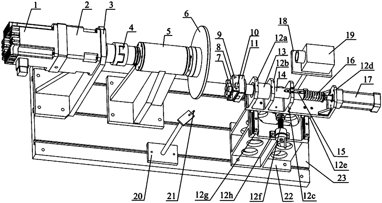
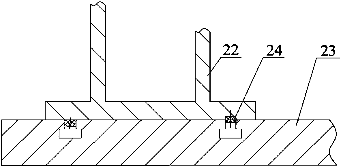
[0030] figure 1The test bench for comprehensive braking performance of the high-speed train brake pads is shown. The servo motor 1 is installed on the support plate 3, and the support plate 3 is arranged on the rectangular base 23. The output shaft of the servo motor arranged horizontally passes through the shaft coupling 4 The outer end of the extended rolling bearing is fixed with a brake disc 6, the rolling bearing is fixed on the base through the rolling bearing seat 5, and the base is arranged on the base 23; T-shaped groove; the bottom plate of the first support seat 22 is movably fixed on the two inverted T-shaped grooves of the base 23 through four bolts, and the left and right sides of the top plate of the first support seat 22 are longitudinally provided with two slide rails 12g , the ball screw 12f is located in the middle of the tw...


PUM

PropertyMeasurementUnit
Sensitivityaaaaaaaaaa

Abstract

The invention provides a test stand for testing a comprehensive brake property of a brake pad of a high speed train. After extending out via a rolling bearing, a shaft of a servo motor is connected with a brake disc; and a cylinder is mounted on a sliding seat in the transverse direction, an output shaft of the cylinder is connected with a push rod after a spring sleeves the output shaft of the cylinder, the push rod penetrates out from a linear bearing and then is successively connected with a three-directional force sensor, a pad support and a mounting plate, a three-directional accelerationsensor is mounted on the mounting plate, friction blocks in different sizes and shapes are fixed on the mounting plate, the sliding seat is in sliding fit with a first supporting seat, a ball screw is longitudinally mounted on the first supporting seat, and a sliding table is fixed on a nut of the ball screw. A base is provided with a thermal imager and a microphone. The test stand has the advantages that the mounting plate is convenient to change, a friction radius is convenient to adjust, functions of vibration resisting and jitter resisting are fulfilled, and the stability of the test stand and the accuracy of tests are improved.

Description

technical field [0001] The invention relates to a performance testing device for train brake pads, in particular to a test bench for testing comprehensive properties such as vibration signals, force signals and frictional heat distribution of the friction interface of the brake pads. Background technique [0002] The brake pads of high-speed trains are designed with multiple friction blocks. During mechanical braking, the friction between these friction blocks and the brake disc is mainly used to perform braking. With the continuous increase of the running speed of high-speed trains, when the train is braking, the unreasonable arrangement of friction blocks will inevitably lead to uneven friction heat distribution of the brake disc in the friction area and excessive temperature difference in the friction area. Furthermore, the wear and tear of each friction block on the brake pad is uneven, which affects the service life of the brake pad; at the same time, it causes abnormal...

Claims


Application Information

Patent Timeline
IPC IPC(8): G01M17/08G01M13/00
CPCG01M13/00G01M17/08
Inventor 莫继良唐斌吴元科范志勇朱旻昊周仲荣
Owner SOUTHWEST JIAOTONG UNIV
Why Eureka
Try Eureka