Calculation method for cavitation coefficient of vertical shaft axial flow paddle turbine power station

A technology of cavitation coefficient and calculation method, which is applied in calculation, data processing applications, instruments, etc., can solve problems such as unsatisfactory, difficult to meet new hydropower engineering requirements for power station cavitation coefficient, large difference, etc.

Active Publication Date: 2021-08-10
CHINA HYDROELECTRIC ENGINEERING CONSULTING GROUP CHENGDU RESEARCH HYDROELECTRIC INVESTIGATION DESIGN AND INSTITUTE
View PDF7 Cites 0 Cited by
  • Summary
  • Abstract
  • Description
  • Claims
  • Application Information

AI Technical Summary

Problems solved by technology

Since this method estimates the cavitation coefficient σ of the power station according to the statistical formula p , there are many statistical formulas of this kind at present, because the water turbine parameter sample data on which each statistical formula is based is before the 1970s and 1980s or a certain water head section or a certain specific speed n s range, there are certain limitations, the results estimated by different statistical formulas for the same hydropower project are different, and some even have large differences, so it is impossible to correctly select
Therefore, both methods 1 and 2 cannot meet the requirements of hydropower engineering for the continuous development of new technologies, new materials, new processes, and new structures. The estimated cavitation coefficient σ p Generally, it is also difficult to meet the new hydropower engineering requirements

Method used


Image

  • Calculation method for cavitation coefficient of vertical shaft axial flow paddle turbine power station
  • Calculation method for cavitation coefficient of vertical shaft axial flow paddle turbine power station
  • Calculation method for cavitation coefficient of vertical shaft axial flow paddle turbine power station

Examples


Embodiment Construction

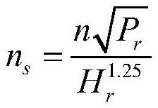
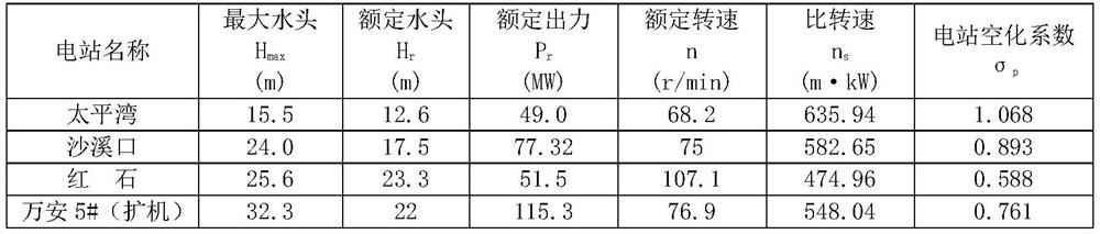
[0013] In the present invention, firstly, by collecting and arranging the data of a large number of well-operated vertical shaft axial flow propeller hydroelectric generating units at home and abroad in the past 30 years, according to the maximum application water head H of the hydro turbine max , divide the data into H max ≤30m and H max For two groups > 30m, the least square method is used to use a large number of turbine parameters as sample data, and regression statistics are used to obtain the cavitation coefficient σ p Calculation formula: when H max ≤30m, When H max When >30m, After doing a lot of calculation and derivation work in the early stage, a more reasonable calculation method was creatively summarized for the cavitation coefficient of the vertical axis axial flow propeller turbine power station. Since the present invention will H max The range is divided, so the vertical axis axial flow paddle turbines corresponding to different water head ranges have d...


PUM


Abstract

The invention relates to a water turbine in a hydropower station, and discloses a calculation method for the cavitation coefficient of a vertical-axis axial-flow paddle-type hydraulic turbine power station, which can more reasonably calculate the cavitation coefficient of a vertical-axis axial-flow paddle-type hydraulic turbine power station to meet new hydropower engineering requirements. The inventive method is as follows: determine the specific rotational speed of the axial flow propeller type water turbine, and described specific rotational speed is denoted as n s ; Determine the maximum application head of the axial flow paddle turbine, and the maximum application head is denoted as H max , and judge H max range; according to H max The formula for calculating the cavitation coefficient of the power station in the corresponding range calculates the cavitation coefficient of the power station, and the cavitation coefficient of the power station is denoted as σ p , the formula for calculating the cavitation coefficient of the power station in the range is: when H max ≤30m, when H max When the distance is greater than 30m, the present invention is applicable to the calculation of the cavitation coefficient of a vertical-axis axial-flow paddle turbine power station, and can better meet the requirements of new hydropower projects.

Description

technical field [0001] The invention relates to a hydroturbine in a hydropower station, in particular to a calculation method for the cavitation coefficient of a vertical-axis flow-to-paddle hydroturbine power station. Background technique [0002] In a hydropower station equipped with a vertical shaft axial flow paddle turbine, the installation elevation of the turbine is the elevation of the centerline of the guide vane of the turbine, and the suction height of the turbine is the elevation difference from the axis of the runner blade to the tail water level of the power station. Raising the suction height and installation elevation of the turbine can reduce the underwater engineering volume and investment of the main powerhouse; while reducing the suction height and installation elevation of the turbine can improve the cavitation performance of the turbine, which is conducive to the stable operation of the unit and prolongs the service life of the unit. Therefore, how to r...

Claims


Application Information

Patent Timeline
Patent Type & Authority Patents(China)
IPC IPC(8): G06Q10/06G06Q50/06
CPCG06Q10/0639G06Q50/06
Inventor 董宏成田迅蒋登云孙文彬刘丁
Owner CHINA HYDROELECTRIC ENGINEERING CONSULTING GROUP CHENGDU RESEARCH HYDROELECTRIC INVESTIGATION DESIGN AND INSTITUTE
Why Eureka
Try Eureka