Check patentability & draft patents in minutes with Patsnap Eureka AI!

Fuel cell flow guiding bipolar plate capable of draining in time and conveniently, and fuel cell system

A fuel cell and bipolar plate technology, used in fuel cells, fuel cell components, circuits, etc., can solve the problems of air waste, increased mechanical power consumption of transporting air or circulating hydrogen, and reducing the efficiency of fuel cell systems. The effect of improving lifespan and efficiency

Inactive Publication Date: 2018-08-17
上海氢尚新能源科技有限公司
View PDF7 Cites 9 Cited by
  • Summary
  • Abstract
  • Description
  • Claims
  • Application Information

AI Technical Summary

Problems solved by technology

[0005] This design is to design more fluid inlets and outlets, and design the diversion groove as a straight-flow groove or a near-flow groove as much as possible. Compared with the traditional serpentine flow path, it does reduce the situation of water blocking. Due to the limitation of the size of the flow plate, the design of this straight channel makes hydrogen and air be discharged from the stack before they can react, a large amount of air is wasted or excess hydrogen is circulated, which will inevitably cause the mechanical work of transporting air or circulating hydrogen. consumption increases, thereby reducing the efficiency of the fuel cell system

Method used


Image

  • Fuel cell flow guiding bipolar plate capable of draining in time and conveniently, and fuel cell system
  • Fuel cell flow guiding bipolar plate capable of draining in time and conveniently, and fuel cell system

Examples


Embodiment 1

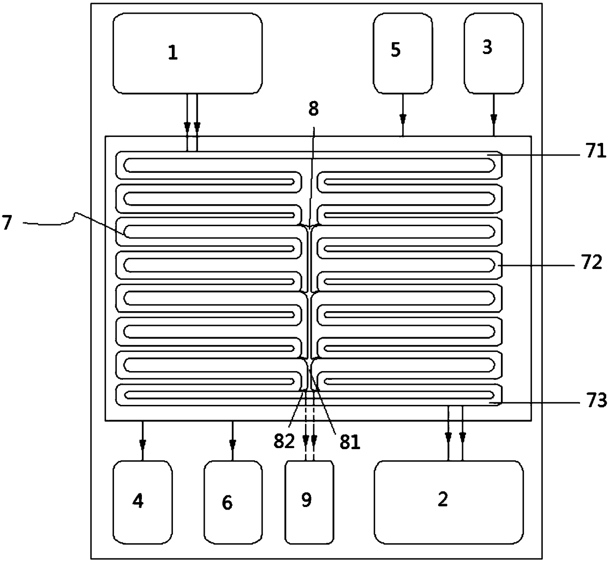
[0029] Such as figure 1 As shown, the fuel cell flow deflector with timely and convenient drainage is composed of a front air guide flow channel plate, a reverse hydrogen guide air flow channel plate, and a middle cooling fluid interlayer. The front air guide flow channel plate is provided with an oxidant inlet 1 and an oxidant Outlet 2, the oxidizer inlet 1, oxidizer outlet 2, fuel inlet 3, fuel outlet 4, cooling fluid inlet 5, cooling fluid outlet 6, oxidizer inlet 1 and oxidizer outlet 2 are connected through oxidant diversion groove 7, oxidant diversion The structure of the groove 7 includes a drainage groove 71 at the entrance, two sets of curved serpentine flow channels 72 arranged side by side in the middle, a confluence groove 73 at the outlet at the bottom, and a drainage channel 8 arranged between the two groups of curved serpentine flow channels 72 The drainage channel 8 includes a straight-flow groove 81 and a plurality of branch grooves 82 arranged on both sides t...

Embodiment 2

[0034] Drainage channels are set on the front air-guiding flow channel plate, and the reverse hydrogen-conducting air flow channel plate is a traditional plate structure without drainage channels. All the other are with embodiment 1.

Embodiment 3

[0036] The length of the straight-flow groove 81 is 1 / 2 of the length of the flow field formed by the oxidant flow diversion groove 7, the width of the straight-flow groove 81 is 1 / 10 of the width of the oxidant flow diversion groove 7, and the width of the branch flow groove 82 is 1 / 10 of the width of the oxidant flow diversion groove 1 / 20 of the width of 7. All the other are with embodiment 1.


PUM


Abstract

The invention belongs to the technical field of a fuel cell, and relates to a fuel cell flow guiding bipolar plate capable of draining in time and conveniently, and a fuel cell system. An oxidizing agent inlet and outlet, a fuel inlet and outlet, and a cooling liquid inlet and outlet, and flow guiding grooves connected with each fluid are formed in the flow guiding bipolar plate; independent and split draining channels are formed in multiple positions of at least one surface of the flow guiding plate; and the draining channels are connected with corresponding flow guiding grooves, so that theaccumulated and generated water in each region where the reactant fluid flows through in the flow guiding grooves can be drained in time through the draining channels. Compared with the prior art, theflow guiding plate can drain water in time, the generated water is shorter in flowing distance in the polar plate flowing channel more smoothly with higher efficiency, thereby effectively eliminatinga phenomenon of water accumulation and water blocking.

Description

technical field [0001] The invention belongs to the technical field of fuel cells, and specifically proposes a new fuel cell diversion bipolar plate and a fuel cell system with timely and convenient drainage. Background technique [0002] A fuel cell is a device that directly converts the chemical energy of hydrogen and oxygen into electrical energy through an electrode reaction. A fuel cell is generally constructed of a plurality of cells, each cell comprising two electrodes (anode and cathode) separated by an electrolyte element and assembled in series with each other to form a fuel cell stack. The electrochemical reaction is achieved by supplying the appropriate reactants to each electrode, ie fuel to one electrode and oxidant to the other, creating a potential difference between the electrodes and thereby generating electrical energy. [0003] In order to supply each electrode with reactants, specific interface elements commonly referred to as "bipolar plates" and arran...

Claims


Application Information

Patent Timeline
Patent Type & Authority Applications(China)
IPC IPC(8): H01M8/026H01M8/0263H01M8/04029
CPCH01M8/026H01M8/0263H01M8/04029Y02E60/50
Inventor 高勇
Owner 上海氢尚新能源科技有限公司
Features
  • R&D
  • Intellectual Property
  • Life Sciences
  • Materials
  • Tech Scout
  • Unparalleled Data Quality
  • Higher Quality Content
  • 60% Fewer Hallucinations
Learn More