Plant electric load distribution method

A technology for load distribution and plant power consumption, applied in the field of electric power, which can solve problems such as inability to maintain load balance and breakage of load balance.

Inactive Publication Date: 2018-08-17
国电建投内蒙古能源有限公司
View PDF1 Cites 0 Cited by
  • Summary
  • Abstract
  • Description
  • Claims
  • Application Information

AI Technical Summary

Problems solved by technology

In this way, the load balance between the two low-voltage split volumes of the high-voltage plant split transformer, which is easy to realize when the auxiliary equipment is double-rowed, is broken.
Therefor

Method used


Image

  • Plant electric load distribution method
  • Plant electric load distribution method
  • Plant electric load distribution method

Examples


Embodiment

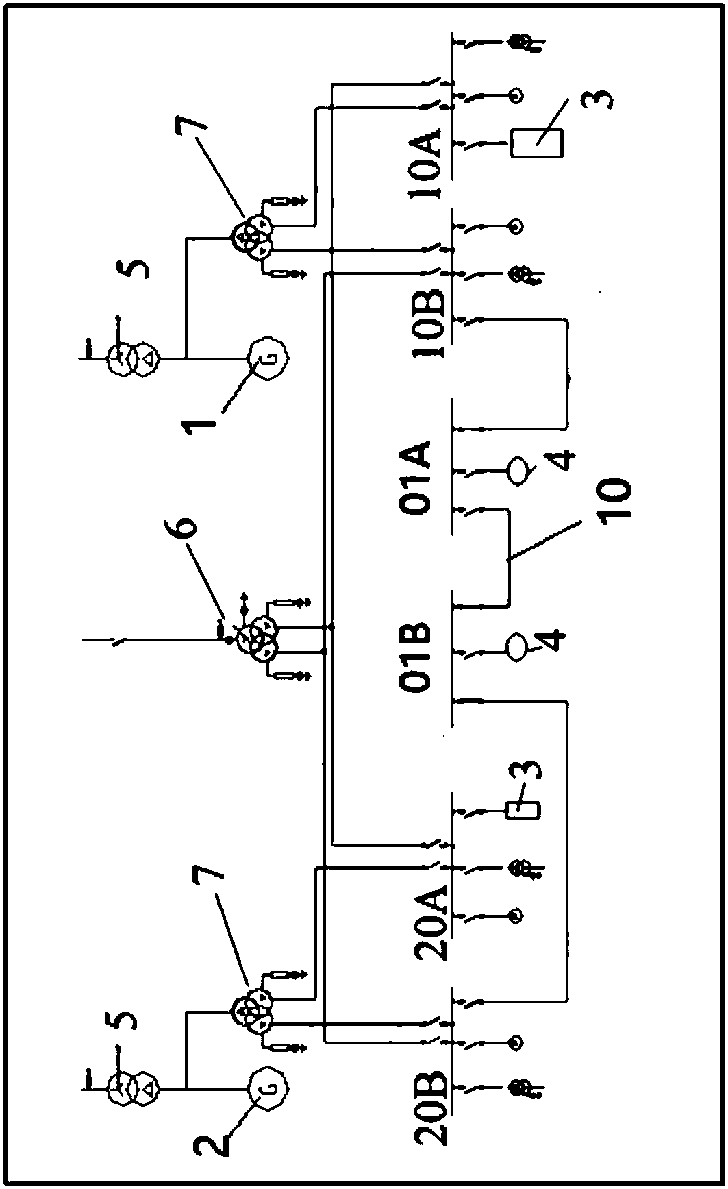
[0027] First, see figure 1 , the invention provides a method for distributing utility power loads, comprising:

[0028] The medium-voltage plant power system includes two units, namely the first unit 1 and the second unit 2, and two sections of medium-voltage working busbars are set up for each unit, of which the first unit 1 is equipped with two sections of medium-voltage working busbars 10A, 10B, the second unit 2 is equipped with two sections of medium-voltage working busbars 20A and 20B, and two sections of medium-voltage common busbars 01A and 01B are set up for the first unit 1 and the second unit 2, of which 01A is drawn from the first unit 1 medium-voltage working bus The busbars 10B and 01B are led from the medium-voltage working busbar 20B of the second unit 2, and the common busbar 01A and the common busbar 01B are provided with a tie switch and a busbar 10.

[0029] Connect the two sections of medium-voltage public buses to the plant working buses tapped to differ...


PUM


Abstract

The invention discloses a plant electric load distribution method. A medium-voltage plant power system includes two units, namely a first unit and a second unit. Each unit is provided with two segments of medium-voltage working busbars. The first and second units are provided with two segments of medium-voltage common busbars which are tapped to plant working busbars of different units and are respectively provided with interconnection switches. The two segments of medium-voltage common busbars are respectively connected to the two segments of medium-voltage working busbars of each unit. Single-row configuration fans of the medium-voltage plant power system are all connected to one of the two segments of medium-voltage working busbars. The unit load in the medium-voltage plant power systemis distributed and connected to the medium-voltage working busbars of each unit. The common load is connected to the medium-voltage common busbars. According to the invention, the medium-voltage common segments are configured separately for the common load of the whole plant, the single-row configuration fans are connected to the medium-voltage working busbars in a unified manner, and the medium-voltage common busbars are connected to the medium-voltage working busbars, so that the load balance after the auxiliary machine single row can be maintained.

Description

Technical field: [0001] The invention relates to the field of electric power technology, in particular to the field of plant power load distribution methods. Background technique: [0002] In the prior art, the power load configuration of the medium-voltage power plant in the power plant is as follows: the electric feed water pump is a starter pump, and there is one set for the two units; the condensate pump and the closed cooling water circulation pump are two sets, one for operation and one for standby; Coal mills are transported in five ways and prepared; primary fan, blower fan and induced draft fan are all configured in a single row; other loads such as auxiliary circulating water pumps, air compressors, rainwater pumps, and belt conveyors are public loads. [0003] After the primary fan, blower fan, and induced draft fan are configured in a single row, from the perspective of process flow, when the unit is running, the three major fans in a single row need to be starte...

Claims


Application Information

Patent Timeline
IPC IPC(8): H02J3/00
CPCH02J3/005
Inventor 顾玉春刘文亮俞基安蔡利军王新宁麦永强白续涛贾潇鸿弓建国乔固刘东吴德利史圯刘波王昭杰
Owner 国电建投内蒙古能源有限公司
Why Eureka
Try Eureka