Three-phase boost rectifier circuit and control method thereof, and an uninterrupted power supply

a rectifier circuit and three-phase technology, applied in the direction of emergency power supply arrangement, power conversion system, three-or-more-wire dc circuit, etc., can solve the problems of reducing the reliability of the boost in the battery state, increasing the cost and circuit complexity, and reducing the efficiency of the boost under battery sta

Active Publication Date: 2019-05-07
KEHUA DATA CO LTD
View PDF13 Cites 0 Cited by
  • Summary
  • Abstract
  • Description
  • Claims
  • Application Information

AI Technical Summary

Benefits of technology

[0006]The invention aims to provide a three-phase boost rectifier circuit with its control methods and uninterrupted power supply, which can ensure the balance of positive and negative bus's voltage without the balancing device under battery operated boost mode, meanwhile improve the efficiency and reliability of the battery operated boost mode.
[0027]Further, when the three-phase boost rectifier circuit works in the battery-operated mode, make the balanced bridge circuit which consist of the fourth bidirectional thyristor SCR6, the second inductor L2, the third switching device and the fourth switching device work, in order to keep the residual capacity of the first battery packs BAT+ as same as the residual capacity of the second battery packs BAT−, as well as maintain the load balance of the positive and negative DC bus.
[0037]Compared with existing technologies, the invention has the following advantages:
[0038]1. The boost rectifier circuit that proposed by the invention can share the power devices such as inductor, switching device, etc. The invention achieves different functions in different conditions by sharing the devices of the topology, which realizes the reuse of power level device, reduces the number of devices, improves the power density of the circuit as well as reduces the cost of the circuit.
[0040]3. The boost rectifier circuit that proposed by the invention can realize the positive and negative bus's independent boosting, also can maintain the balance of the positive and negative bus's voltage without the extra balance device. The invention allows the positive and negative bus bar to carry unbalanced load, which improves the reliability of the battery mode as well as reduces the cost.
[0042]5. The invention achieves balance function by adding a fourth bidirectional thyristor SCR6, sharing the second inductor L2, the third switching transistors Q3 and the fourth switching transistors Q4 of the rectifier boost topology. On the one hand, the invention can ensure the remaining capacity of the first battery packs BAT+ and the second battery packs BAT− are consistent. On the other hand, the invention can ensure the load balance on the positive and negative DC bus by controlling the balance bridge.

Problems solved by technology

With the technical proposal, the cost and circuit complexity are increased, meanwhile the reliability of the boost in battery state is decreased.
At the same time, the balancing device generates additional power consumption while maintain the balance of the positive and negative bus's voltage, which reduces the efficiency of the boost under battery state.

Method used


Image

  • Three-phase boost rectifier circuit and control method thereof, and an uninterrupted power supply
  • Three-phase boost rectifier circuit and control method thereof, and an uninterrupted power supply
  • Three-phase boost rectifier circuit and control method thereof, and an uninterrupted power supply

Examples


embodiment 1

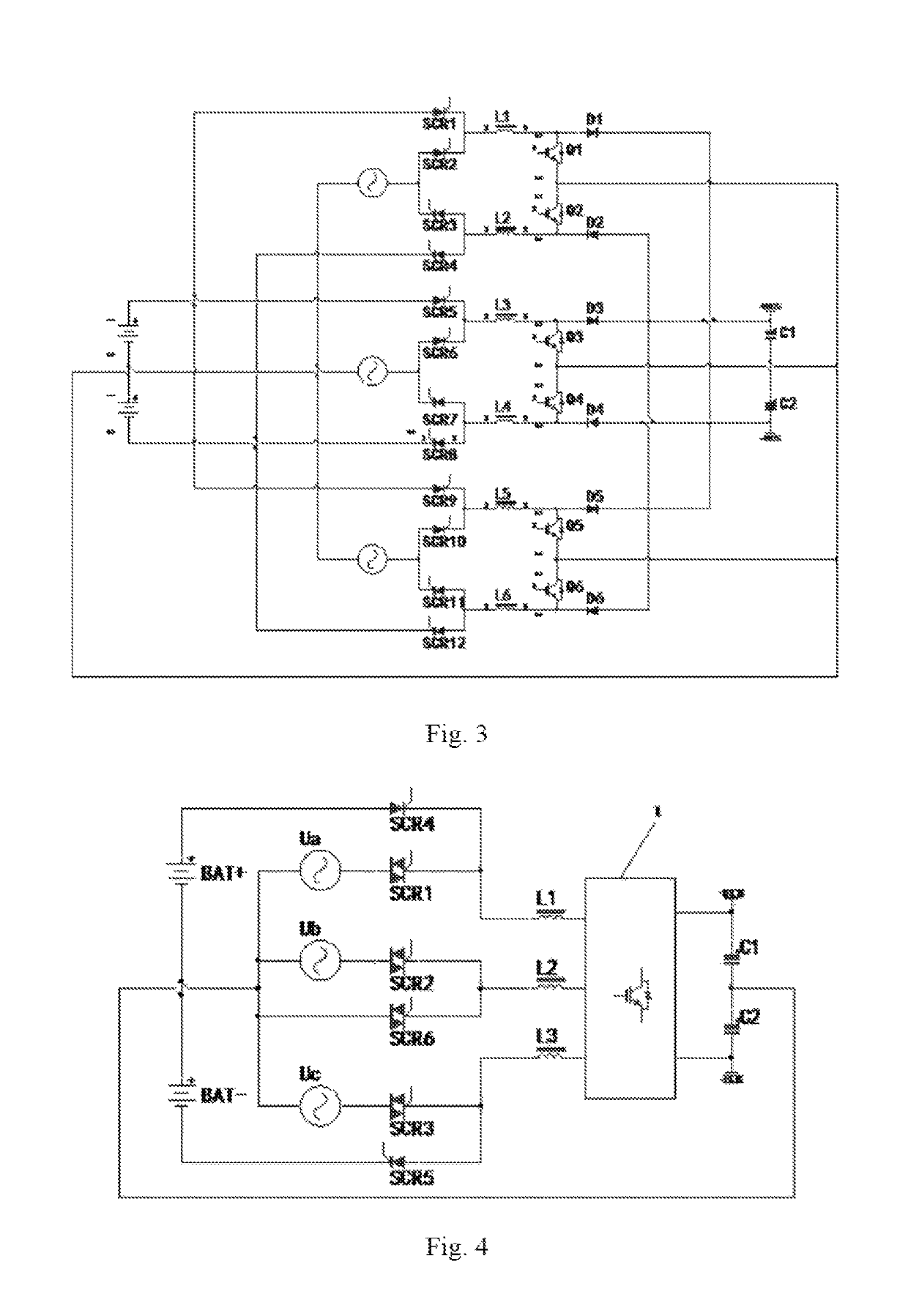
[0064]As shown in FIG. 4, a three-phase boost rectifier circuit, comprising positive battery packs BAT+, second battery packs BAT−, and a boost rectifier module; the boost rectifier module comprising a first bidirectional thyristor SCR1, a second bidirectional thyristor SCR2, a third bidirectional thyristor SCR3, a fourth bidirectional thyristor SCR6, a first unidirectional thyristor SCR4, a second unidirectional thyristor SCR5, a first inductor L1, a second inductor L2, a third inductor L3, a three-phase fully controlled rectifier bridge, a first capacitor C1, a second capacitor C2; one end of the first bidirectional thyristor SCR1, one end of the second bidirectional thyristor SCR2 and one end of the third bidirectional thyristor SCR3 are respectively connected to the first phase of three-phase power, the second phase of three-phase power and the third phase of three-phase power; the anode of the first unidirectional thyristor SCR4 and the cathode of the second unidirectional thyr...

embodiment 2

[0090]As shown in FIG. 19, this embodiment provide a three-phase boost rectifier circuit, comprising positive battery packs BAT+, second battery packs BAT−, and a boost rectifier module; the boost rectifier module comprising a first bidirectional thyristor SCR1, a second bidirectional thyristor SCR2, a third bidirectional thyristor SCR3, a fourth bidirectional thyristor SCR6, a first unidirectional thyristor SCR4, a second unidirectional thyristor SCR5, a first inductor L1, a second inductor L2, a third inductor L3, a three-phase fully controlled rectifier bridge, a first capacitor C1, a second capacitor C2; one end of the first bidirectional thyristor SCR1, one end of the second bidirectional thyristor SCR2 and one end of the third bidirectional thyristor SCR3 are respectively connected to the first phase of three-phase power, the second phase of three-phase power and the third phase of three-phase power; the anode of the first unidirectional thyristor SCR4 and the cathode of the s...

embodiment 3

[0092]As shown in FIG. 20, this embodiment provide a three-phase boost rectifier circuit, comprising positive battery packs BAT+, second battery packs BAT−, and a boost rectifier module; the boost rectifier module comprising a first bidirectional thyristor SCR1, a second bidirectional thyristor SCR2, a third bidirectional thyristor SCR3, a fourth bidirectional thyristor SCR6, a first unidirectional thyristor SCR4, a second unidirectional thyristor SCR5, a first inductor L1, a second inductor L2, a third inductor L3, a three-phase fully controlled rectifier bridge, a first capacitor C1, a second capacitor C2; one end of the first bidirectional thyristor SCR1, one end of the second bidirectional thyristor SCR2 and one end of the third bidirectional thyristor SCR3 are respectively connected to the first phase of three-phase power, the second phase of three-phase power and the third phase of three-phase power; the anode of the first unidirectional thyristor SCR4 and the cathode of the s...


PUM


Abstract

The invention relates to a three-phase boost rectifier circuit and a control, method thereof, and an uninterrupted power supply which contains at least first battery packs BAT+, second battery packs BAT−, and a boost rectifier module; the boost rectifier module comprises a first bidirectional thyristor SCR1, a second bidirectional thyristor SCR2, a third bidirectional thyristor SCR3, a fourth bidirectional thyristor SCR6, a first unidirectional thyristor SCR4, a second unidirectional thyristor SCR5, a first inductor L1, a second inductor L2, a third inductor L3, a three-phase fully controlled rectifier bridge, a first capacitor C1 and a second capacitor C2. The invention can ensure the balance of positive and negative bus's voltage without the balancing device under battery operated boost mode, while improving the efficiency and reliability of the battery operated boost mode.

Description

CROSS REFERENCE TO RELATED APPLICATIONS[0001]This application is the national phase entry of International Application No. PCT / CN2015 / 088721, filed on Sep. 1, 2015, which is based upon and claims priority to Chinese Application No. CN201510495221.5, filed on Aug. 13, 2015, the entire contents of which are incorporated herein by reference.TECHNICAL FIELD[0002]The invention relates to the field of boost rectifier module and uninterrupted power supply, especially for a three-phase boost rectifier circuit with its control methods and uninterrupted power supply.BACKGROUND OF THE INVENTION[0003]The traditional duce-phase uninterrupted power supply (UPS) generally uses three-phase half budge rectifier boost topology that comprising a single battery pact which can only control the sum of voltage of positive and negative bus. In order to maintain the balance of the positive and negative bus's voltage, current technology usually adds a balancing device, as shown in FIG. 1. With the technical ...

Claims


Application Information

Patent Timeline
Patent Type & Authority Patents(United States)
IPC IPC(8): H02J1/08H02M7/217H02M7/219H02J9/06H02M1/10H02M7/487
CPCH02M7/2173H02J9/06H02M7/219H02M1/10H02M7/487
Inventor WANG, ZHIDONGZENG, YIZHANGCHEN, CHENGHUISU, NINGHUAN
Owner KEHUA DATA CO LTD
Why Eureka
Try Eureka