Service flow division implementation method and device
A technology for implementing methods and services, applied in the field of communications, which can solve problems such as inability to install shunt filters, and inability to dynamically introduce ULCL
- Summary
- Abstract
- Description
- Claims
- Application Information
AI Technical Summary
Problems solved by technology
Method used
Image
Examples
Embodiment 1
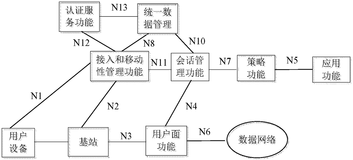
[0238] Figure 5a The flow chart of the PFDF providing the packet flow description information provided by the application to the appropriate UPF provided by Embodiment 1 of the present invention. This embodiment is based on Figure 4aIn the architecture shown, the PFDF is arranged separately from the NEF. Such as Figure 5a shown, including the following steps:
[0239] Step 501: The application (such as a third-party service capability server / application server (Services CapabilityServer / Application Server, SCS / AS for short)) sends a PFD management request message to the NEF, the PFD management request message carries the SCS / AS identifier, and the application provides Service Provider (SP for short) reference identifier, external Application Id (application identifier), PFD requested to be added or modified, and corresponding location information.
[0240] Among them, an application may deploy application servers in multiple regions to achieve load sharing or nearby acc...
Embodiment 2
[0265] Figure 5b It is a flow chart of the PCF providing the packet flow description information provided by the application to the appropriate UPF according to the second embodiment of the present invention. This embodiment is based on Figure 4c In the architecture shown, the third-party application provides the PFD to the PCF through the NEF. Such as Figure 5b shown, including the following steps:
[0266] Step 5a01: The application (such as SCS / AS) sends a PFD management request message to the NEF, and the PFD management request message carries the SCS / AS identifier, the SP reference identifier, the external Application Id, the PFD requested to be added or modified, and the corresponding location information .
[0267] Among them, an application may deploy application servers in multiple regions to achieve load sharing or nearby access. Therefore, for the same external Application Id, the PFDs corresponding to different location information are usually different.
...
Embodiment 3
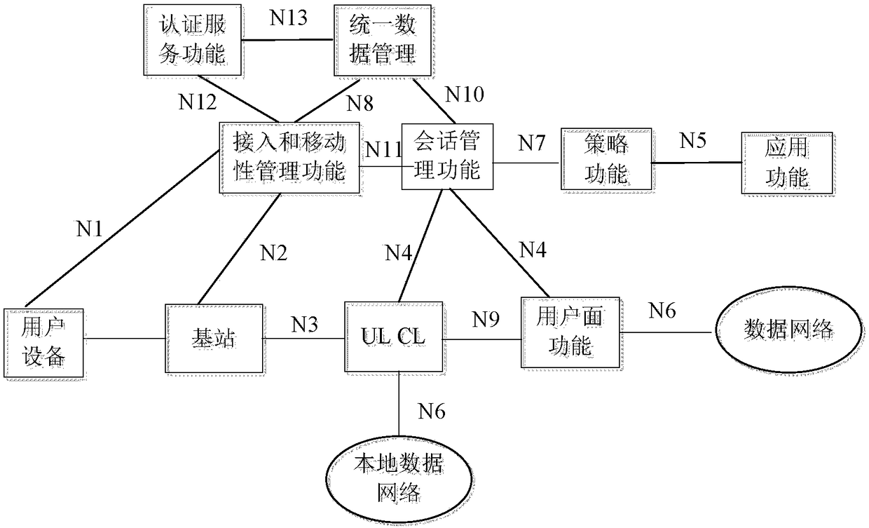
[0291] Figure 6 It is a flow chart of introducing UL CL when a PDU session is established, and activating distribution rules by SMF. Such as Figure 6 shown, including the following steps:
[0292] Step 601: UE initiates an attach process and completes network registration;
[0293] Step 602: The UE sends a PDU session establishment request message to the AMF, and the PDU session establishment request message carries a user identifier and a data network name (Data Network Name, DN Name);
[0294] Step 603: After the AMF selects a SMF, forward the PDU session establishment request message to the selected SMF;
[0295] Step 604: The SMF interacts with User Data Management (UDM for short), obtains subscription information of the user, and verifies the UE. Wherein, the subscription information of the user carries a UL CL permission indication;
[0296] Step 605: the SMF assigns an IP address to the UE. The SMF sends a policy request message to the PCF, and the policy reques...
PUM
 Abstract
Description
Claims
Application Information
 - R&D
- Intellectual Property
- Life Sciences
- Materials
- Tech Scout
- Unparalleled Data Quality
- Higher Quality Content
- 60% Fewer Hallucinations
Browse by: Latest US Patents, China's latest patents, Technical Efficacy Thesaurus, Application Domain, Technology Topic, Popular Technical Reports.
© 2025 PatSnap. All rights reserved.Legal|Privacy policy|Modern Slavery Act Transparency Statement|Sitemap|About US| Contact US: help@patsnap.com


