Ore impurity precipitation machine

A technology of impurity precipitation and settler, which is used in precipitation separation, control of the inclination of precipitation equipment, sedimentation tank, etc., can solve the problems of difficult ore pulp and impurity shutdown, avoid material accumulation problems, ensure continuity, and increase contact area. Effect

Active Publication Date: 2018-08-21
新疆喀拉通克矿业有限责任公司
View PDF5 Cites 3 Cited by
  • Summary
  • Abstract
  • Description
  • Claims
  • Application Information

AI Technical Summary

Benefits of technology

This new design allows for continuous processing without stopping or reducing productivity by replacing an entire tank containing suspended solids (SS) instead of just adding more solid). It also includes various features such as a mixer equipped with a special type of tubing called a T - shaped tape, which helps distribute the SS uniformly throughout it while keeping them from sinking into other parts of the system. Additionally, there's another embodiment where multiple magnetic controls are used together to improve consistency and efficiency in delivering high quality products like concrete.

Problems solved by technology

This patented technical problem addressed in the current design relational solution described in the previous study describes the challenges associated with efficiently removing harmful metals from materials while minimizing operative costs due to high levels of emissions generated through flue gas purification systems (FGSP). Current methods require large amounts of space and involve complicated steps like stopping rotation before moving parts towards other directions. Additionally, there may exist issues related to improving the performance of conventional apparatus designs without adding extra components beyond what they were initially designed.

Method used


Image

  • Ore impurity precipitation machine
  • Ore impurity precipitation machine
  • Ore impurity precipitation machine

Examples


Embodiment

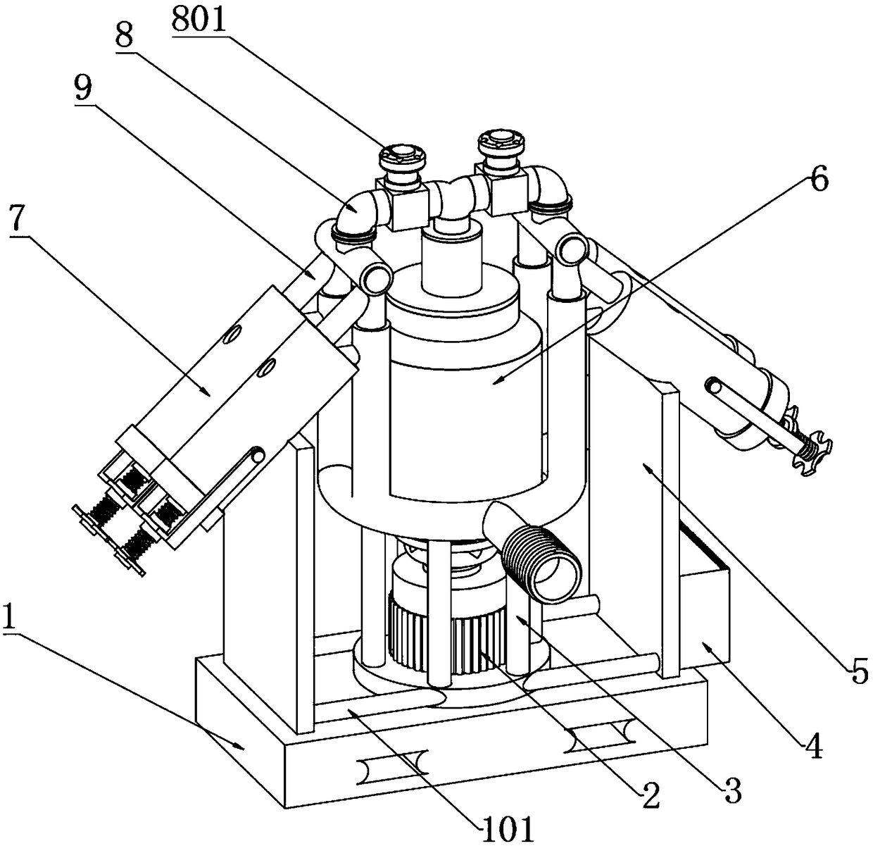
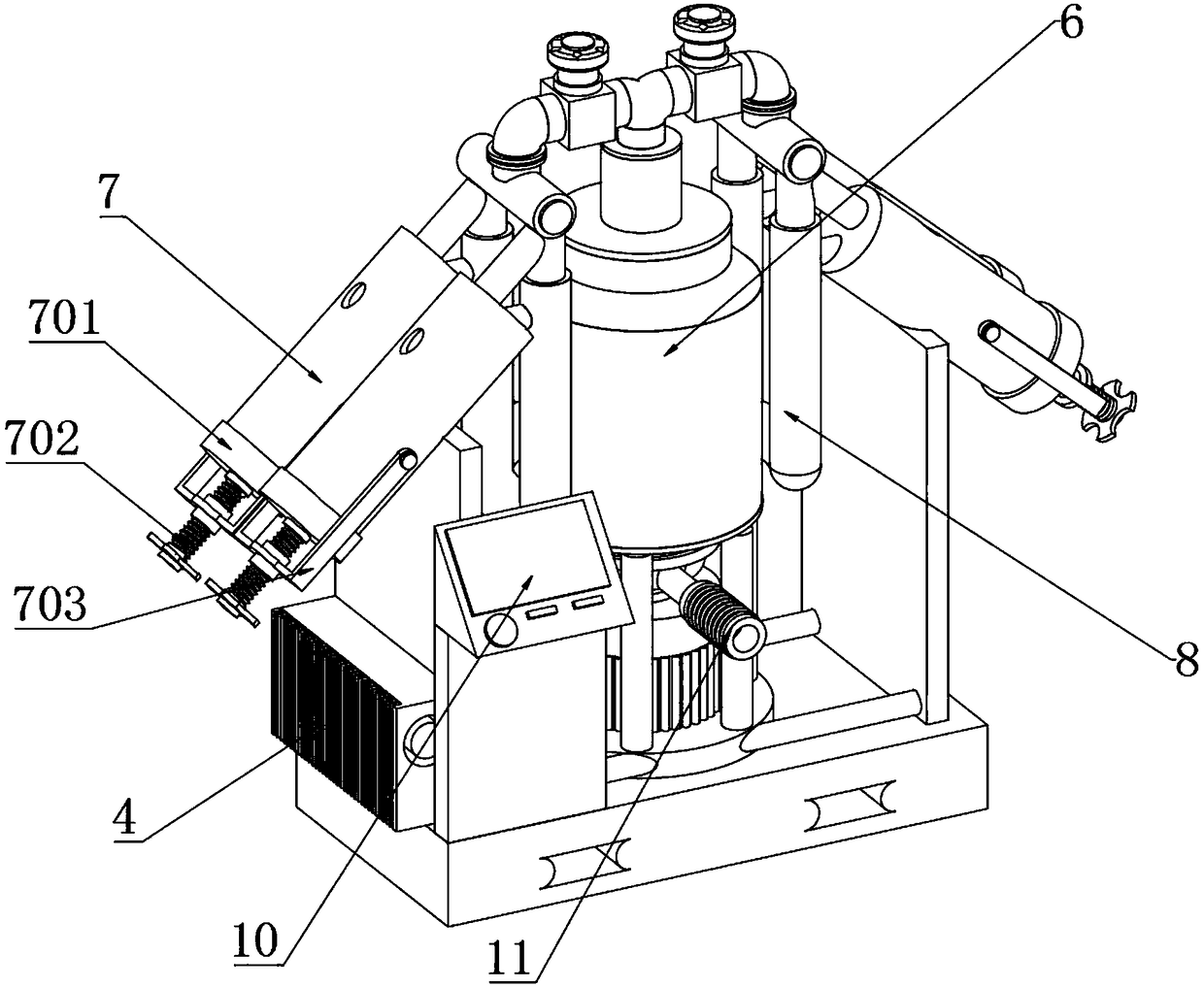
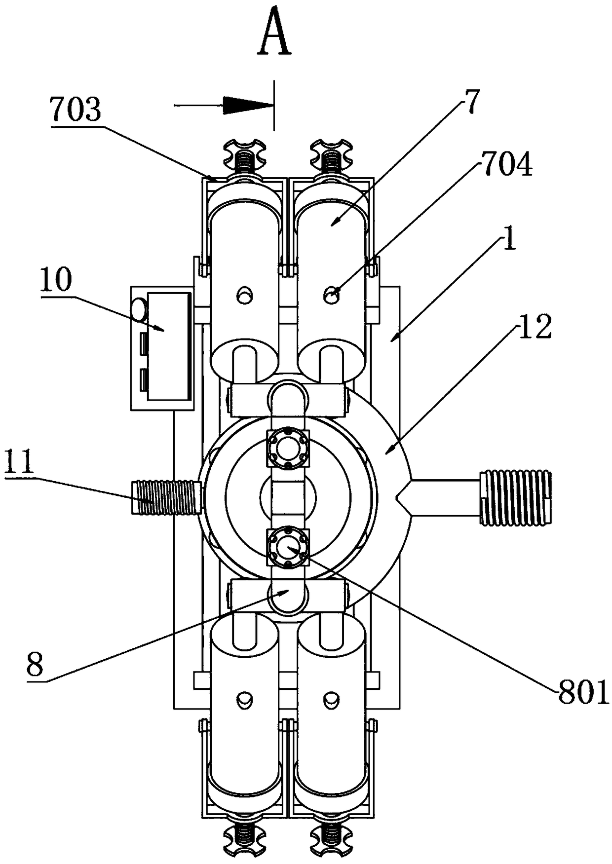
[0039] as attached figure 1 to attach Figure 10 Shown:

[0040] The present invention provides a mineral impurity sedimentation machine, including a support base plate 1, a servo motor 2, a support column 3, a controller 4, a support plate 5, a mixing homogenizer 6, a settler 7, a T-shaped pipe 8, a bifurcated pipe 9, Control panel 10, feed pipe 11, discharge pipe 12, feed deflector 13, I-shaped fixed frame body 101, rotating shaft 601, homogeneous paddle 602, push block 603, push paddle 604, sedimentation cylinder 701, Tightening column 702, fixed frame 703, observation hole 704, electromagnetic control valve 801, material distribution pipe 1101, chemical precipitation purification inner cylinder 70101, return plate 70102 and positioning groove 70201, and the center of the bottom of the support base 1 is fixed with a servo motor 2, and the periphery of the bottom of the servo motor 2 is fixed to the inner bottom end of the vertical rectangular support plate 5 provided at b...


PUM


Abstract

The invention provides an ore impurity precipitation machine. The machine comprises a bottom support plate, a backflow plate and a positioning tank, wherein a servo motor is fixedly arranged in the center of the bottom of the bottom support plate, the periphery of the bottom of the servo motor is fixed at the bottom ends of inner sides of vertical rectangular support plates arranged at two ends ofthe top of the bottom support plate through a surrounding I-shaped fixing rack; a rotating shaft at the top of the servo motor is rotationally connected in a mixing homogenizer on the upper side, andsix support columns surrounding the servo motor are arranged between the mixing homogenizer and the bottom support plate. T-shaped pipes and electromagnetic control valves are arranged, the T-shapedpipes are arranged at the top of the mixing homogenizer, two symmetric electromagnetic control valves are arranged on the T-shaped pipes, so that two symmetric structures are arranged on two sides ofthe mixing homogenizer, the device on one side can be reserved for normal operation during replacement of a precipitation barrel, the continuity of the process can be guaranteed, and the production pause cost is reduced.

Description


Claims


Application Information

Patent Timeline
Owner 新疆喀拉通克矿业有限责任公司
Why Eureka
Try Eureka