Punch for packaging mechanical parts

A technology for packaging machinery and stamping machines, which is applied in the field of stamping machines, can solve problems that affect stamping quality, easily generate high temperature, and easily tilt molds, etc., and achieve the effects of prolonging service life, improving stamping efficiency, and improving heat conduction efficiency

Inactive Publication Date: 2018-08-21
WUJIANG HEXIN MASCH FACTORY
View PDF0 Cites 0 Cited by
  • Summary
  • Abstract
  • Description
  • Claims
  • Application Information

AI Technical Summary

Problems solved by technology

[0003] However, when the existing stamping machines are processing parts, the workpiece is fixed manually, which has a great risk. The stamping machine is prone to high temperature after long-term use. If it is not handled in time, it will cause wear and damage of the abrasive tool. Abrasives
In addition, the stamping machine will produce a lot of vibration during the working process, and the mold is easy to tilt, which greatly affects the stamping quality. Therefore, a stamping machine for packaging mechanical parts is designed. The stamping machine for packaging mechanical parts has good heat dissipation and stamping efficiency. High, with strong practicality

Method used


Image

  • Punch for packaging mechanical parts
  • Punch for packaging mechanical parts
  • Punch for packaging mechanical parts

Examples


Embodiment Construction

[0015] The following will clearly and completely describe the technical solutions in the embodiments of the present invention with reference to the accompanying drawings in the embodiments of the present invention. Obviously, the described embodiments are only some, not all, embodiments of the present invention. Based on the embodiments of the present invention, all other embodiments obtained by persons of ordinary skill in the art without making creative efforts belong to the protection scope of the present invention.

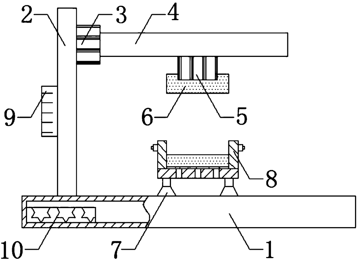
[0016] see figure 1 , figure 1 It is a structural schematic diagram of the present invention, a stamping machine for packaging mechanical parts, including a base 1, a first guide rail 2 is installed on the left side of the upper surface of the base 1, and a first step is slidably connected to the right side of the first guide rail 2 Motor 3, the first stepping motor 3 slides up and down on the first guide rail 2, the second guide rail 4 is installed on the ri...


PUM


Abstract

The invention relates to a punch for packaging mechanical parts. The punch comprises a pedestal, a first guide rail is installed on the left side of an upper surface of the pedestal, the right side ofthe first guide rail is in sliding connection with a first stepper motor, a second guide rail is installed on the right side of the first stepper motor, the bottom surface of the second guide rail isin sliding connection with a second stepper motor, the bottom surface of the second stepper motor is fixedly connected with an upper mold through a bolt, the middle part of an upper surface of the pedestal is fixedly connected with a punching mechanism through an adjusting nut, the punching mechanism comprises a bottom plate, a shell, a lower mold and locking nuts, the upper surface of the bottomplate is fixedly connected with the shell, the bottom end of an inner wall of the shell is provided with a the lower mold, the upper ends on the left and right sides of the shell are both provided with the locking nuts, the middle part on the left side of the first guide rail is provided with a stepper motor controller, and the bottom end of an inner wall on the left side of the pedestal is fixedly connected with a power source.

Description

technical field [0001] The invention belongs to the technical field of punching machines, and in particular relates to a punching machine for packing mechanical parts. Background technique [0002] The punching machine drives the flywheel through the motor, and through the clutch, the transmission gear drives the crank linkage mechanism to move the slider up and down, and drives the drawing die to form the steel plate. The so-called double action means that the press has two sliders, which are divided into an inner slider and an outer slider. The inner slider drives the punch or die of the mold, and the outer slider drives the blankholder on the mold. When the blank holder first moves to press the edge of the steel plate, the inner slider moves again to stretch. [0003] However, when the existing stamping machines are processing parts, the workpiece is fixed manually, which has a great risk. After a long time of use, the stamping machine is easy to generate high temperatur...

Claims


Application Information

Patent Timeline
Patent Type & Authority Applications(China)
IPC IPC(8): B21D22/22B21D37/16B21D37/10F16F15/02
CPCB21D22/22B21D37/10B21D37/16F16F15/02
Inventor 陆国强
Owner WUJIANG HEXIN MASCH FACTORY
Why Eureka
Try Eureka