Attracting, lifting and rotating device

A technology of rotating device and adsorption block, applied in auxiliary devices, auxiliary welding equipment, welding/cutting auxiliary equipment, etc., to achieve the effect of ingenious structural design

Pending Publication Date: 2018-08-21
QUICK INTELLIGENT EQUIP CO LTD
View PDF0 Cites 0 Cited by
  • Summary
  • Abstract
  • Description
  • Claims
  • Application Information

AI Technical Summary

Problems solved by technology

[0004] The purpose of the present invention is to provide an adsorption lifting rotating device to solve the technical problems of the rotary welding of the jig and the lifting of the jig

Method used


Image

  • Attracting, lifting and rotating device
  • Attracting, lifting and rotating device
  • Attracting, lifting and rotating device

Examples


Embodiment Construction

[0029] The present invention is described in further detail now in conjunction with accompanying drawing. These drawings are all simplified schematic diagrams, which only illustrate the basic structure of the present invention in a schematic manner, so they only show the configurations related to the present invention.

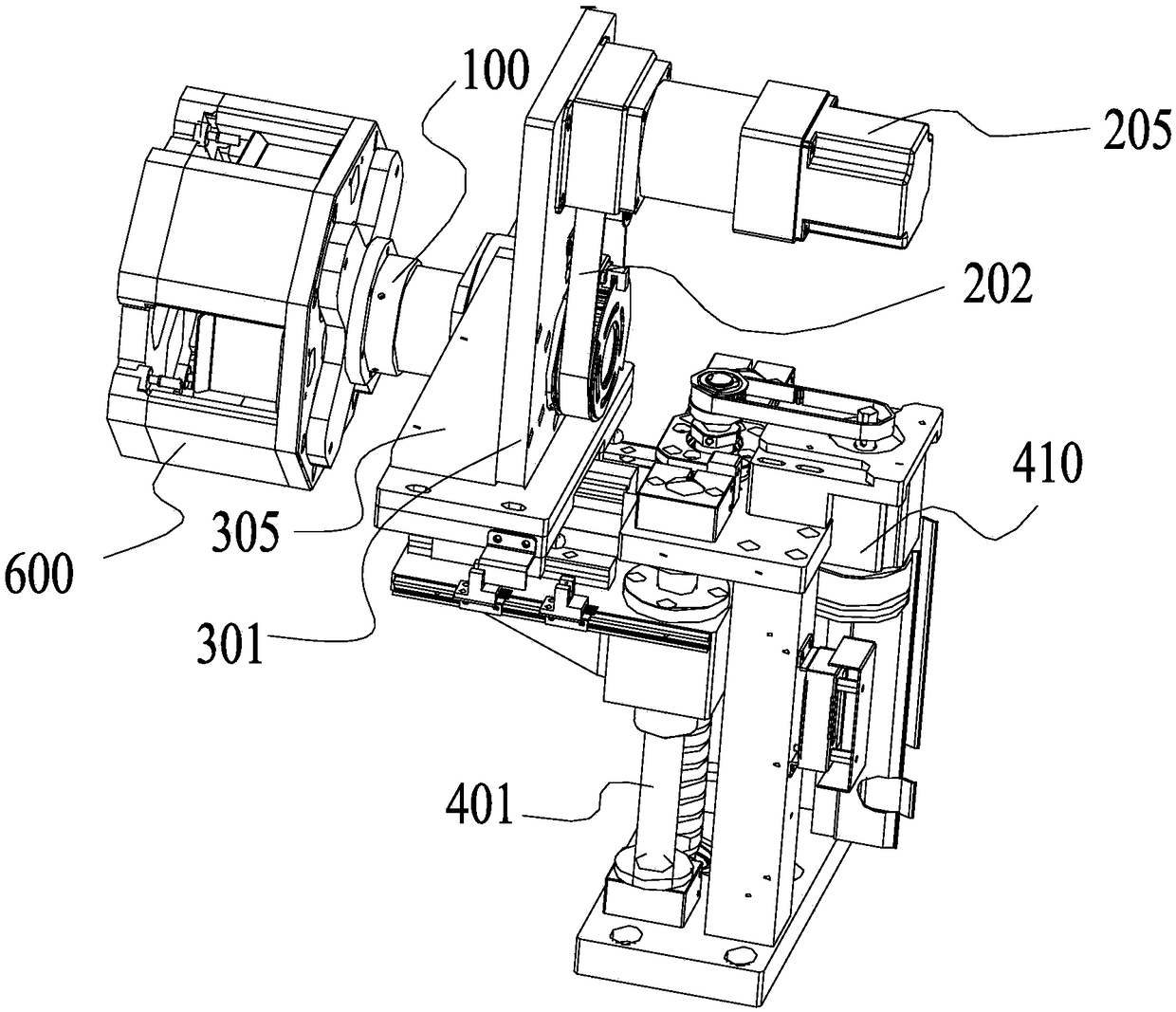
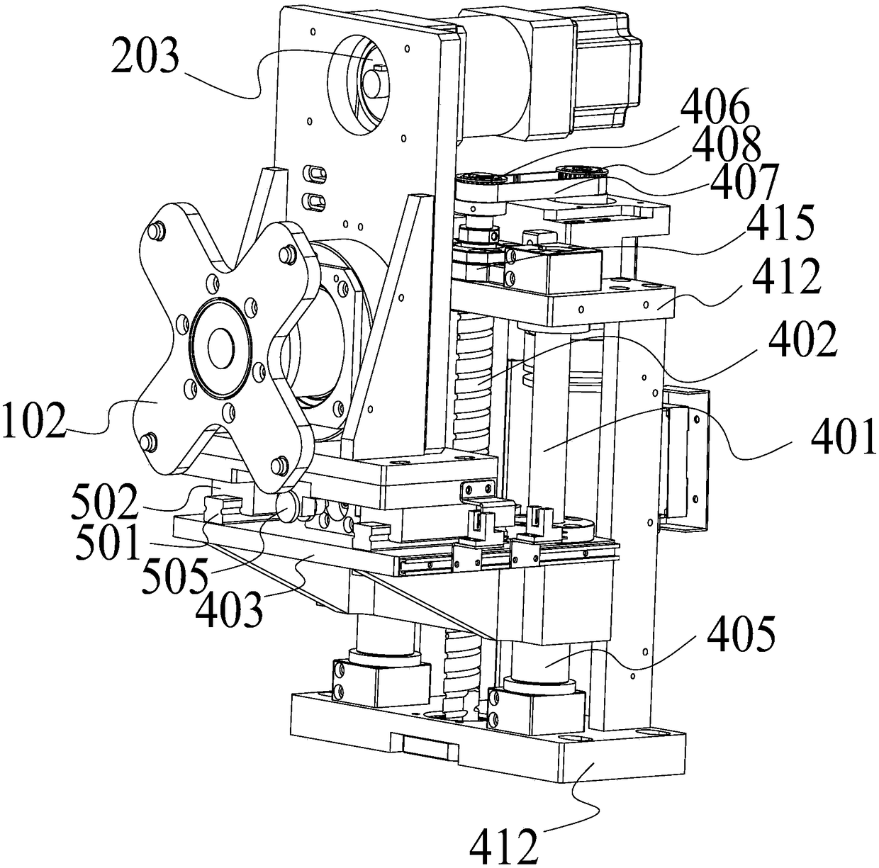
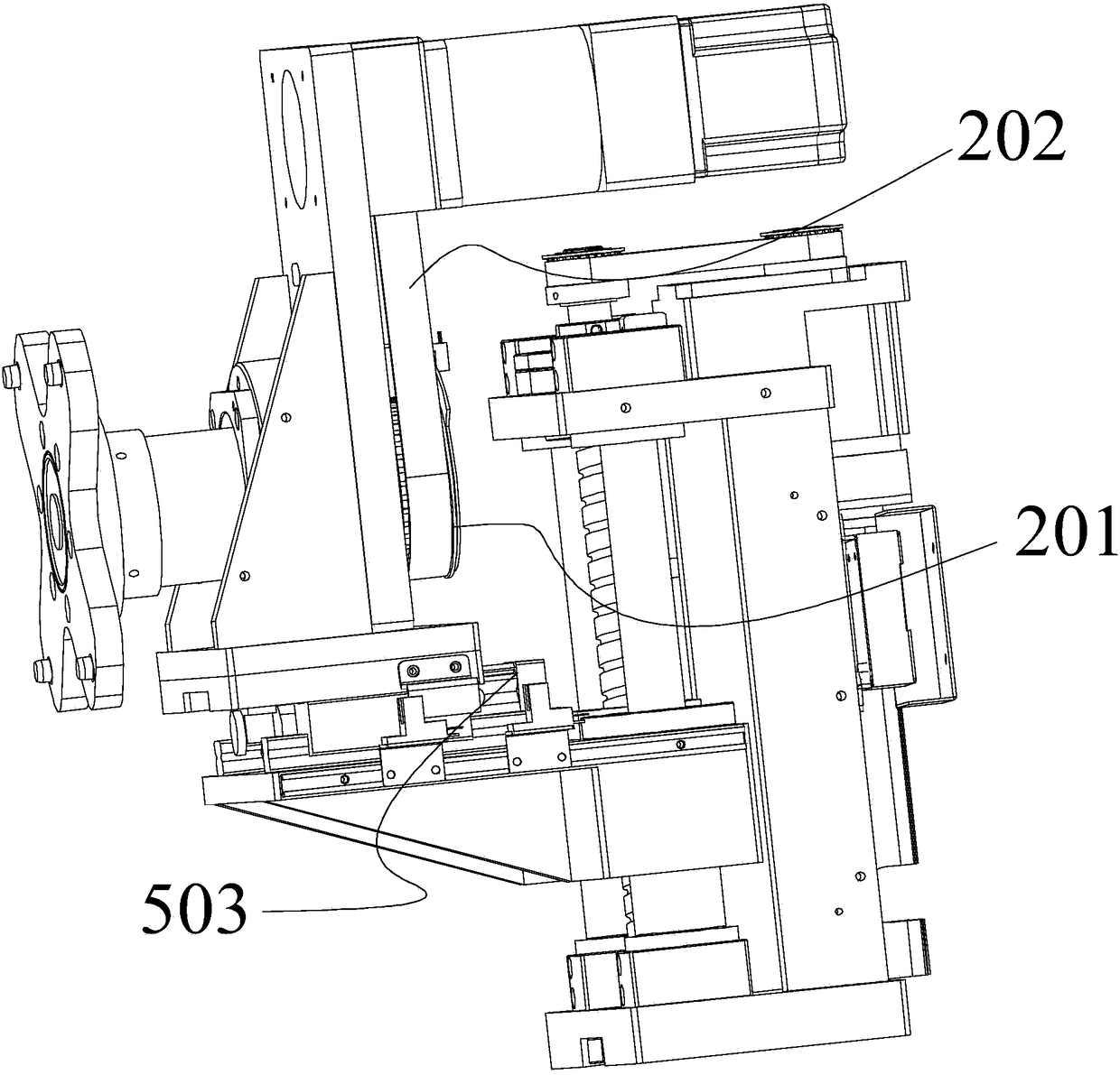
[0030] see Figure 1 to Figure 3 As shown, the present invention provides an adsorption, lifting and rotating device, including: a jig adsorption block 100, a rotating mechanism and a lifting mechanism.

[0031] The fixture adsorption block 100 , the end surface of the fixture adsorption block 100 suitable for absorbing the fixture 600 is provided with a magnetic attraction portion 102 . Specifically, the magnetic attraction part 102 is provided with a strong magnet, such as but not limited to neodymium iron boron.

[0032] The rotating mechanism includes a passive runner 201 coaxially arranged with the fixture adsorption block 100, a driving runner 203 conn...


PUM


Abstract

The invention relates to the technical field of mechanical engineering and automation, in particular to an attracting, lifting and rotating device. The device comprises a jig attracting block, a rotating mechanism and a lifting mechanism. The end face, suitable for attracting a jig, of the jig attracting block is provided with a magnetic attraction part. The rotating mechanism comprises a driven rotating wheel coaxial with the jig attracting block, a driving rotating wheel connected with the driven rotating wheel through a conveying belt and a first driving motor connected with the driving rotating wheel; the driving rotating wheel is rotatably arranged on a vertical plate, the jig attracting block penetrates through the vertical plate, and the end, penetrating out of the vertical plate and located on the same side as the driving rotating wheel, of the jig attracting block is connected with the driven rotating wheel. The lifting mechanism comprises a pair of guide pillars, a lead screwarranged between the guide columns and a connecting frame in threaded connection with the lead screw; the connecting frame slidably sleeves the guide pillars; the upper end of the lead screw is connected with a driving assembly suitable for driving the lead screw to rotate.

Description

technical field [0001] The invention relates to the technical fields of mechanical engineering and automation, in particular to an adsorption lifting rotating device. Background technique [0002] In the era of rapid development of mechanical automation, for the welding process of jigs, especially when the jig needs to be welded in a circumferential direction, it is necessary to design a device that can select the jig itself so that the jig can rotate in the circumferential direction during the welding process. . [0003] Generally, in the process of mechanized production, the processing of a jig is usually a continuous multi-process operation. In order to cooperate with the devices of other processes, the device for welding the jig often needs to design a lifting structure so that the welding The pre-welded jig or the jig after welding is easy to transfer. Contents of the invention [0004] The purpose of the present invention is to provide an adsorption lifting and rot...

Claims


Application Information

Patent Timeline
Patent Type & Authority Applications(China)
IPC IPC(8): B23K37/00
CPCB23K37/00
Inventor 窦小明包成姜加伟
Owner QUICK INTELLIGENT EQUIP CO LTD
Why Eureka
Try Eureka