Assembling mechanism applied to heat exchangers and assembling method thereof

An assembly mechanism and assembly method technology, applied in metal processing, metal processing equipment, manufacturing tools, etc., can solve the problems of long time consumption and low heat exchanger assembly efficiency, so as to reduce assembly or assembly costs and reduce the number of workers. Effect

Active Publication Date: 2018-08-21
GREE ELECTRIC APPLIANCES INC
View PDF10 Cites 11 Cited by
  • Summary
  • Abstract
  • Description
  • Claims
  • Application Information

AI Technical Summary

Problems solved by technology

[0006] The main purpose of the present invention is to provide an assembly mechanism and assembly method for heat exc

Method used


Image

  • Assembling mechanism applied to heat exchangers and assembling method thereof
  • Assembling mechanism applied to heat exchangers and assembling method thereof
  • Assembling mechanism applied to heat exchangers and assembling method thereof

Examples


Embodiment 1

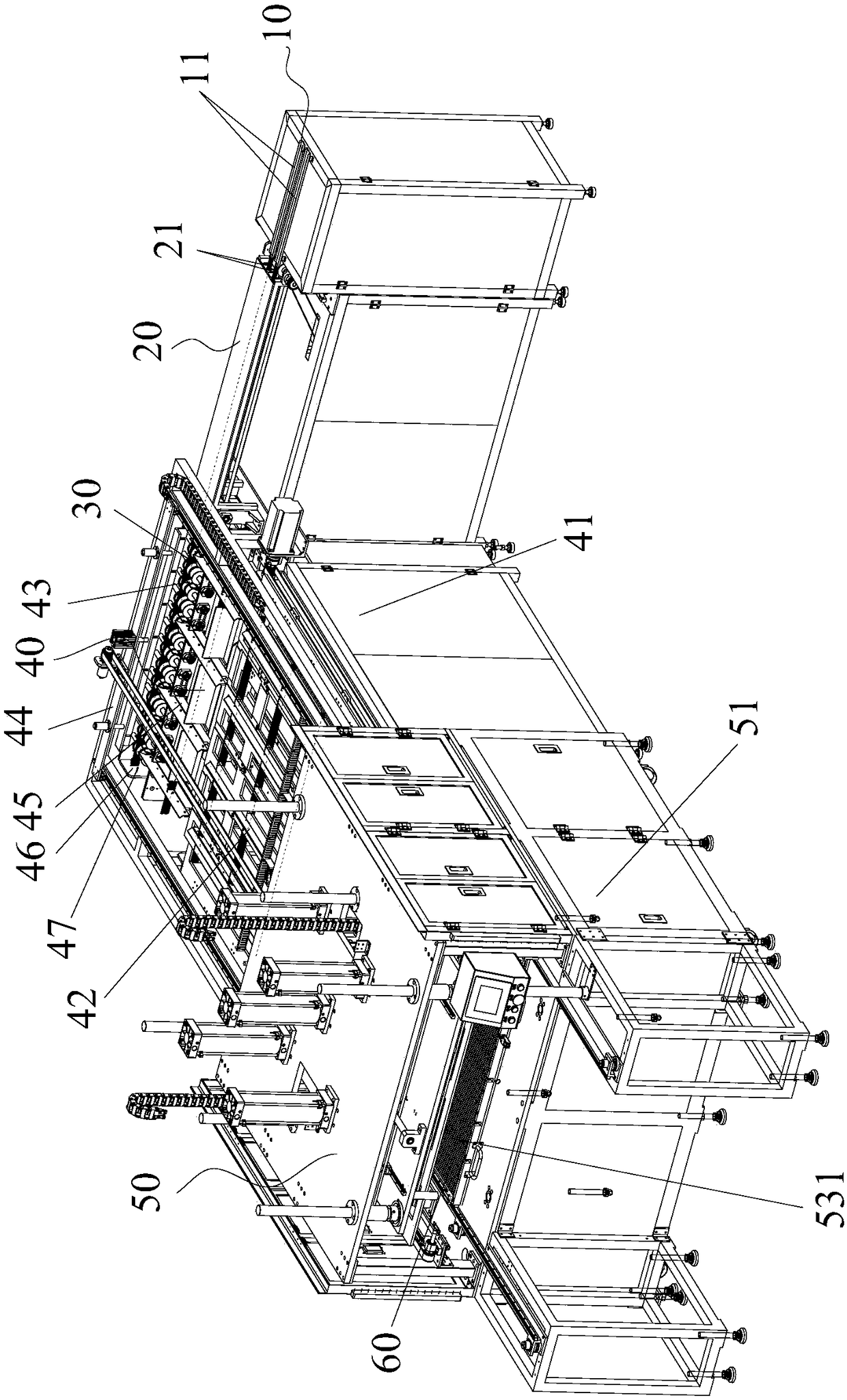
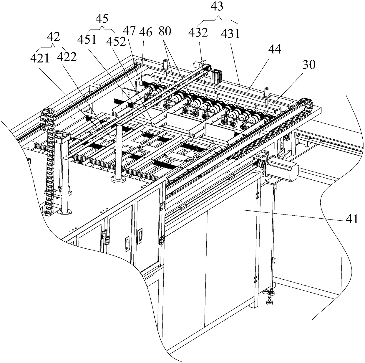
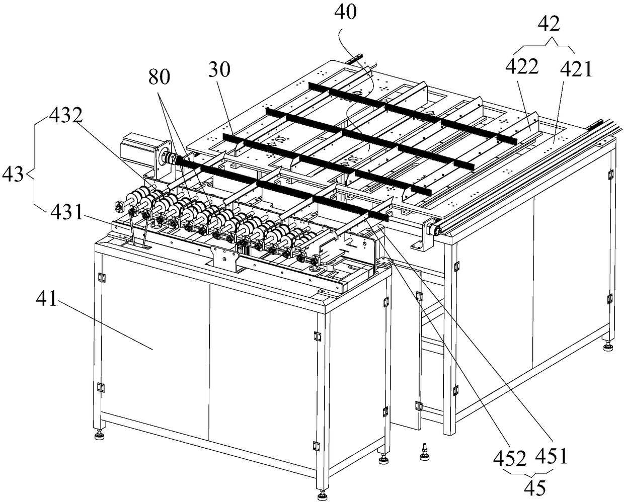
[0050] Such as figure 1 As shown, the assembly mechanism for the heat exchanger includes a material receiving device 10 , a conveying device 20 , a summarizing device 40 and an assembling device 50 . Wherein, the conveying device 20 is connected with the material receiving device 10 , and the conveying device 20 conveys the heat exchange fins 30 on the material receiving device 10 . The summarizing device 40 can be docked with the conveying device 20 , and the summarizing device 40 turns over the heat exchange fins 30 transported to the summarizing device 40 , and transports the turned heat exchange fins 30 . The assembly device 50 is located downstream of the induction device 40 , and the heat exchange fins 30 delivered to the assembly device 50 are assembled with the flat tubes 60 to be crimped to form a heat exchanger.

[0051] Applying the technical solution of this embodiment, in the process of assembling the heat exchanger, the heat exchange fins 30 pass through the mat...

Embodiment 2

[0130] The difference between the assembly mechanism of the second embodiment and the first embodiment is that the internal structure of the assembly device 50 moves differently.

[0131] In this embodiment, step S3 includes:

[0132] Step S31: the second platform 421 of the induction device 40 moves into the assembly device 50;

[0133] Step S32: the claw driving part 522 of the clamping assembly of the assembly device 50 drives the claw 521 to move, and the claw 521 clamps the heat exchange fin 30 on the second platform 421;

[0134] Step S33: The flat tube tray 531 of the flat tube mounting assembly of the assembly device 50 moves toward the pressing plate 532 of the flat tube mounting assembly, so that the flat tube 60 to be crimped in the flat tube mounting assembly is pressed into the U-shape of the heat exchange fin 30 in the slot.

[0135] Such as Image 6 As shown, the second platform 421 drives the heat exchanging fins 30 into the assembly device 50 , and the claw...

Embodiment 3

[0137] The difference between the assembly mechanism of the third embodiment and the first embodiment lies in that the structure of the assembly device 50 is different.

[0138] Such as Figure 7 As shown, the assembly device 50 also includes a flat tube hanger 56 . Wherein, the flat tube hook 56 is fixed on the pressing plate 532 , and the flat tube hook 56 passes through the flat tube tray 531 , the assembly device 50 does not include the suspension structure 54 , and the flat tube hook 56 is used instead of the suspension structure 54 . Specifically, during the assembly process of the flat tube 60 to be crimped and the heat exchange fin 30 , the flat tube hook 56 is pressed down synchronously with the pressing plate 532 , and also achieves the function of hanging and positioning the heat exchange fin 30 .

[0139] Optionally, there are a plurality of flat tube hooks 56 , and the plurality of flat tube hooks 56 are arranged at intervals along the extending direction of the ...


PUM


Abstract

The invention provides an assembling mechanism applied to heat exchangers and an assembling method thereof. The assembling mechanism applied to heat exchangers comprises a receiving device, a conveying device connected with the receiving device and used for conveying heat exchange fins on the receiving device, a sorting device butted with the conveying device and used for turning the heat exchangefins conveyed to the sorting device and conveying the turned heat exchange fins, and an assembling device located at a downstream position of the sorting device and used for assembling the heat exchange fins conveyed into the assembling device with flat tubes to be pressed and connected to form heat exchangers. Through the assembling mechanism applied to heat exchangers and the assembling methodthereof, the problems of low assembling efficiency and long assembling time of the heat exchangers in the prior art are effectively solved.

Description

technical field [0001] The invention relates to the technical field of assembly of heat exchangers, in particular to an assembly mechanism and an assembly method for heat exchangers. Background technique [0002] At present, the traditional heat exchanger is formed by filling corrugated strip fins and flat tubes, binding them and welding them. However, the heat exchanger has the following structural disadvantages: [0003] (1) Due to the combined structural characteristics of corrugated strip fins and flat tubes, condensed water is not easy to discharge and easily forms a water bridge, which increases the wind resistance of the heat exchanger and affects the heat exchange effect; [0004] (2) Under the heating condition of the heat exchanger, condensed water is prone to accumulate on the heat exchanger, resulting in frosting and ice blockage on the heat exchanger, which reduces the heating effect of the heat exchanger. [0005] In order to solve the drainage defects of tra...

Claims


Application Information

Patent Timeline
IPC IPC(8): B23P19/00
CPCB23P19/001B23P19/002B23P19/007B23P2700/10
Inventor 符众贺扬吴迎文叶剑辉钟明生李路倪雪辉王叶
Owner GREE ELECTRIC APPLIANCES INC
Why Eureka
Try Eureka