Radiator fin separating, taking and conveying equipment

A radiator and fin technology, which is applied in the field of radiator fin separation and delivery equipment, can solve the problems of heavy labor burden and low efficiency, and achieve the effects of reducing labor burden, improving work efficiency, and increasing friction

Active Publication Date: 2018-08-21
WEIFANG UNIVERSITY
View PDF16 Cites 0 Cited by
  • Summary
  • Abstract
  • Description
  • Claims
  • Application Information

AI Technical Summary

Problems solved by technology

At present, it is necessary to manually separate the stacks of radiator fins one by one, which is inefficient and labor-intensive

Method used


Image

  • Radiator fin separating, taking and conveying equipment
  • Radiator fin separating, taking and conveying equipment
  • Radiator fin separating, taking and conveying equipment

Examples


Embodiment Construction

[0030] In order to make the object, technical solution and advantages of the present invention clearer, the present invention will be further described in detail below in conjunction with the accompanying drawings and embodiments. It should be understood that the specific embodiments described here are only used to explain the present invention, not to limit the present invention.

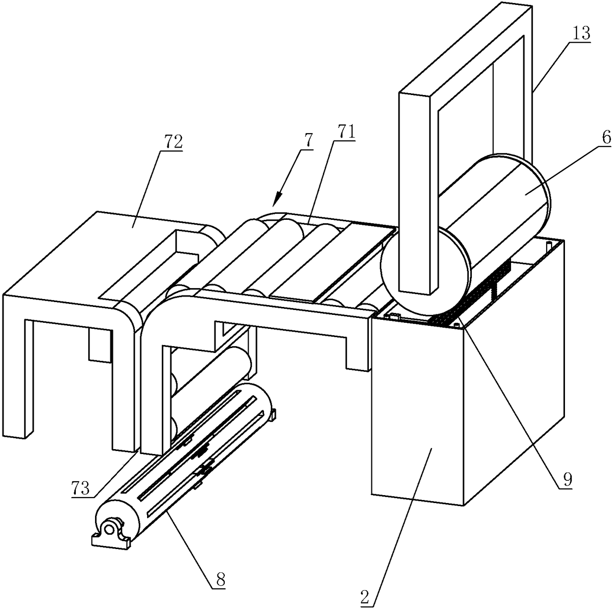
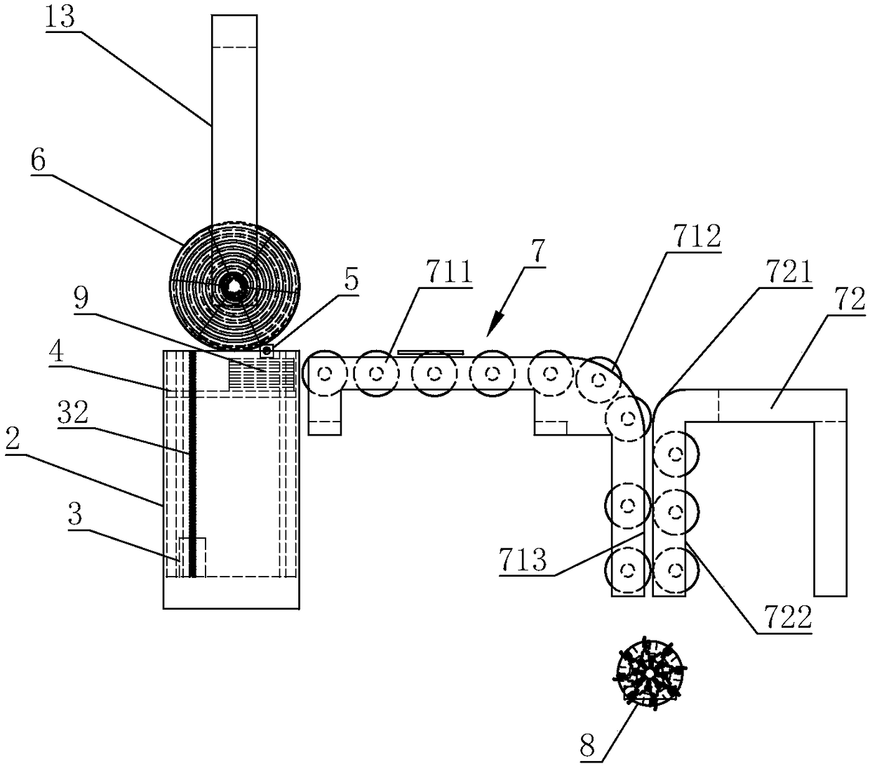
[0031] Refer to attached figure 1 , figure 2 , the radiator fin separation and delivery equipment of the present embodiment includes a controller 1, a feed bin 2 and a conveying device 7 arranged at the rear end of the feed bin 2. A wire extending to the top of the feed bin 2 is vertically provided in the feed bin 2. The rod 32, the lead screw 32 is connected with the servo motor 3 in transmission, the lead screw 32 is threadedly connected with the lifting pallet 4, the top of the feed bin 2 is provided with a bracket 13, and the bracket is provided with a fin separation driven by the first power...


PUM


Abstract

The invention discloses radiator fin separating, taking and conveying equipment. The radiator fin separating, taking and conveying equipment comprises a controller, a bin and a conveying device arranged at the rear end of the bin, wherein a lead screw driven to rotate by a servo motor is vertically arranged in the bin, a lifting supporting plate is connected to the lead screw in a threaded manner,and a fin separating roller and a detection sensor used for detecting radiator fins are arranged at the top end of the bin. A radiator fin scattering clamp is arranged below the conveying device. Theradiator fin scattering clamp comprises a rotating drum, multiple clamping grooves are axially formed in the outer peripheral surface of the rotating drum at intervals, a clamping mechanism is arranged in each clamping groove, the rotating drum is driven to rotate by a third power device, and the detection sensor, a controller of the servo motor, a first power device, a second power device and the third power device are electrically connected with the controller. According to the radiator fin separating, taking and conveying equipment, the stacked radiator fins can be automatically separated,taken and conveyed, and the working efficiency is improved.

Description

technical field [0001] The invention relates to the technical field of radiator fin production devices, in particular to a radiator fin separation and delivery equipment. Background technique [0002] Adding fins on the radiator can increase the heat dissipation area of ​​the radiator and improve the heat dissipation capacity of the radiator, so radiator fins are widely used in radiators. In the production process of the radiator fins, the radiator fins are stacked and stacked during the process of cutting the radiator fins by the cutting machine. After the stacked radiator fins are transferred to the next process, such as the cleaning process, the stacks of radiator fins need to be separated one by one. At present, it is necessary to manually separate the stacks of radiator fins one by one, which is inefficient and labor-intensive. Contents of the invention [0003] The technical problem to be solved by the present invention is to provide a radiator fin separation and d...

Claims


Application Information

Patent Timeline
Patent Type & Authority Applications(China)
IPC IPC(8): B65G47/82B65G47/90B65G47/74
CPCB65G47/74B65G47/82B65G47/90B65G2201/0214
Inventor 解福祥宋健徐萌萌李晓晓
Owner WEIFANG UNIVERSITY
Why Eureka
Try Eureka