
Integrated ventilation pavilion for fuel gas cabin of underground comprehensive pipe gallery

A technology of integrated pipe gallery and gas, applied in the direction of ventilation system, vertical pipes, underwater structures, etc., can solve the problems such as the influence of the ground wind pavilion on the urban landscape, the ventilation equipment should not be arranged, and the wind pavilion is large in size, etc. Achieve the effect of reducing risk points, reducing volume and high safety

Pending Publication Date: 2018-08-21
BEIJING GENERAL MUNICIPAL ENG DESIGN & RES INST
View PDF6 Cites 4 Cited by
  • Summary
  • Abstract
  • Description
  • Claims
  • Application Information

AI Technical Summary

Problems solved by technology

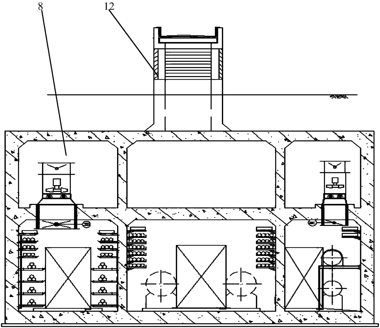
Please see attached figure 1 The existing setting of this kind of fan and wind pavilion does not comply with the second article of 9.3.9 of the "Code for Fire Protection Design of Buildings" GB 50016-2014: the exhaust equipment should not be arranged in underground or semi-underground buildings (rooms) Inside
Moreover, the arrangement of fan equipment on the mezzanine will result in a large volume of the mezzanine; in order to meet the reliability of the civil structure, the civil wind pavilion has added support such as structural columns, which has resulted in a large volume of the wind pavilion and the impact of the ground wind pavilion on the urban landscape

Method used


Image

  • Integrated ventilation pavilion for fuel gas cabin of underground comprehensive pipe gallery
  • Integrated ventilation pavilion for fuel gas cabin of underground comprehensive pipe gallery
  • Integrated ventilation pavilion for fuel gas cabin of underground comprehensive pipe gallery

Examples


Embodiment Construction

[0020] The specific embodiments of the present invention will be further described below in conjunction with the accompanying drawings.

[0021] The following examples are only examples for clearly illustrating the present invention, rather than limiting the implementation of the present invention. For those of ordinary skill in the art, on the basis of the following descriptions, other different forms of changes or changes can also be made, and these obvious changes or changes that belong to the spirit of the present invention are still within the protection scope of the present invention middle.

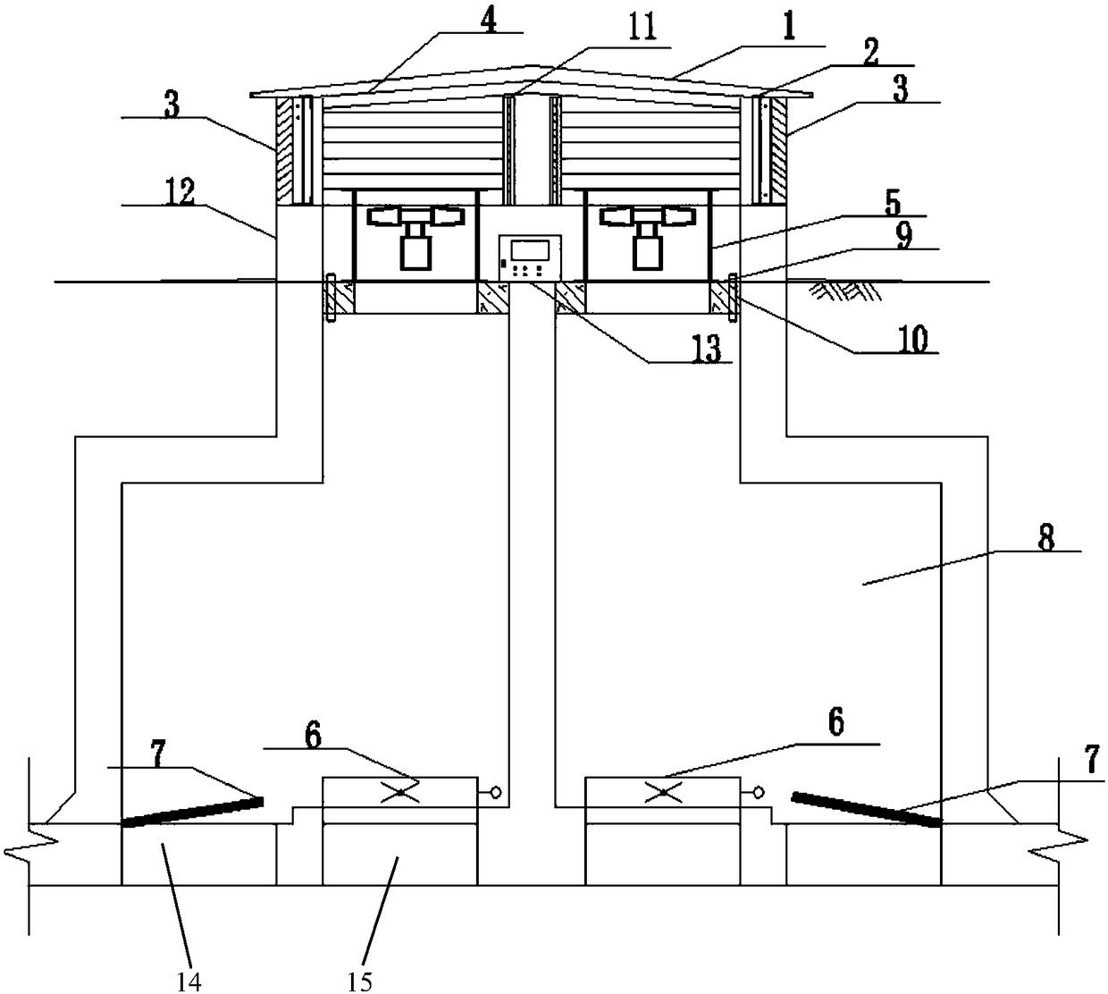
[0022] In the present invention, a hole is opened above the gas cabin to make a vertical ventilation shaft, and then the supply and exhaust fans and the control cabinet (box) are arranged above the ground level, and safety factors such as anti-theft and explosion-proof are considered. Steel structure wind pavilion with open louvers.

[0023] An integrated air pavilion with a gas ...


PUM


Abstract

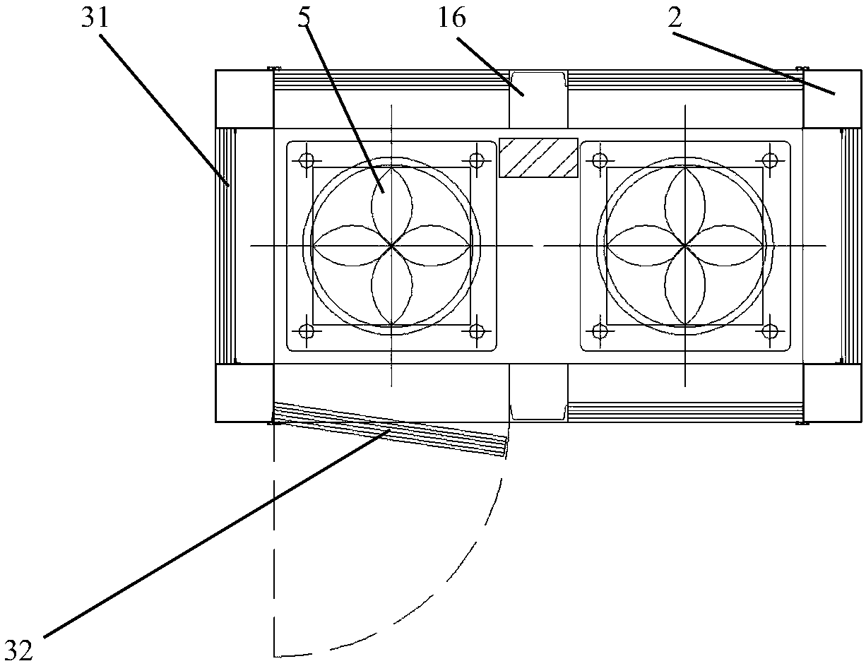
The invention provides an integrated ventilation pavilion for a fuel gas cabin of an underground comprehensive pipe gallery. The integrated ventilation pavilion comprises an overground ventilation pavilion and an underground pipe gallery interlayer, wherein the fuel gas cabin and an air duct are arranged at the lower layer of the pipe gallery interlayer; the top of the fuel gas cabin is provided with a manhole communicated with the pipe gallery interlayer; the manhole is sealed by a damping cover plate; the top of the air duct is provided with an air vent communicated with the pipe gallery interlayer; the air vent is provided with an air valve; a vertical ventilating shaft is formed above the manhole and the air vent and is communicated with the pipe gallery interlayer and the overground ventilation pavilion; a fan foundation is inlaid in a ground shaft mouth of the ventilating shaft; the ventilation pavilion is of a modularized steel structure; the ventilation pavilion is located on the structural wall of the ventilating shaft; the ventilation pavilion is provided with a top steel support made of steel; four corners of the ventilation pavilion are fixedly supported on vertically-arranged angle steels with the equal height; rainproof louvers are vertically inlaid between adjacent angle steels; a fan is fixed above the fan foundation in the ventilation pavilion; and the fan is connected to a control cabinet through a control cable. The integrated ventilation pavilion provided by the invention can solve the risk that an exhaust fan of the fuel gas cabin is arranged in the semi-underground space as well as eliminate the influence of the ground ventilation pavilion on urban landscapes.

Description

technical field [0001] The invention relates to the technical field of wind kiosks for comprehensive utility corridors, in particular to an integrated wind kiosk for gas cabins of underground comprehensive utility tunnels. Background technique [0002] The risk of the gas cabin of the underground comprehensive pipe corridor has always existed. The civil wind pavilion of the gas cabin of the underground comprehensive pipe gallery is set on the ground, and the fan is installed in the interlayer of the underground equipment. The fan and the wind pavilion are set separately. Please see attached figure 1 The existing setting of this kind of fan and wind pavilion does not comply with the second article of 9.3.9 of the "Code for Fire Protection Design of Buildings" GB 50016-2014: the exhaust equipment should not be arranged in underground or semi-underground buildings (rooms) Inside. Moreover, the arrangement of fan equipment on the mezzanine will result in a large volume of the ...

Claims


Application Information

Patent Timeline
Patent Type & Authority Applications(China)
IPC IPC(8): E02D29/045E04F17/00F24F7/007
CPCF24F7/007E02D29/10E04F17/00
Inventor 李科董骥赵兴海
Owner BEIJING GENERAL MUNICIPAL ENG DESIGN & RES INST
Learn More