Connecting structure for prefabricated concrete wall panels and steel columns and construction method thereof

A technology of prefabricated wall panels and connecting structures, applied to walls, building components, building structures, etc., can solve problems such as poor integrity and poor earthquake resistance, achieve good integrity, reduce welding operations, and prevent rust

Pending Publication Date: 2018-08-21
李藏柱
View PDF8 Cites 6 Cited by
  • Summary
  • Abstract
  • Description
  • Claims
  • Application Information

AI Technical Summary

Problems solved by technology

[0002] During the installation process of concrete prefabricated wall panels in the process of building construction, metal materials such as steel plates or steel bars are often used on the concrete prefabricated wall panels to be welded or bolted to steel columns such as H-shaped steel to realize the fixed installation of concrete prefabricated wall panels. However, there is no connection between two adjacent concrete prefabricated wall panels, so that the joints between the prefabricated panels and the steel structure have the disadvantages of poor integrity and poor earthquake resistance

Method used


Image

  • Connecting structure for prefabricated concrete wall panels and steel columns and construction method thereof
  • Connecting structure for prefabricated concrete wall panels and steel columns and construction method thereof
  • Connecting structure for prefabricated concrete wall panels and steel columns and construction method thereof

Examples


Embodiment 1

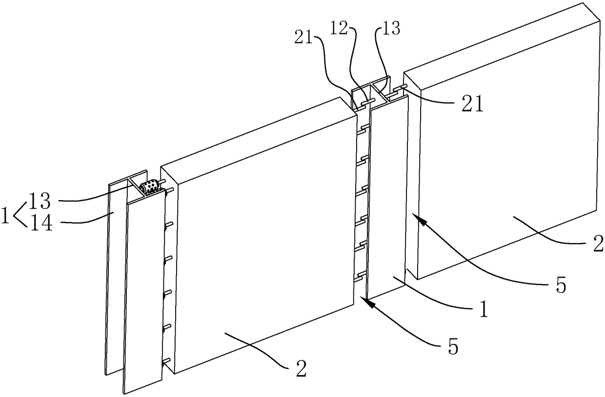
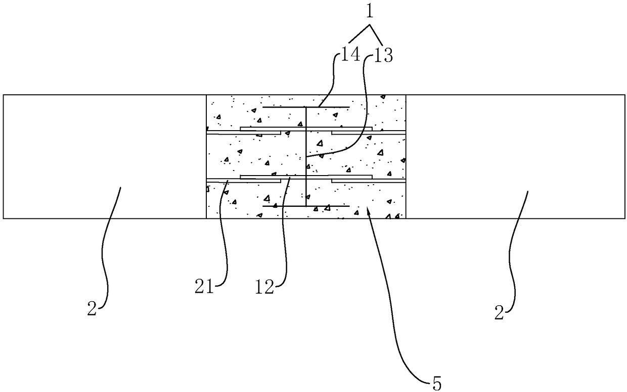
[0063] A connection structure between concrete prefabricated wall panels and steel columns, such as figure 1 and figure 2 As shown, it includes a shaped steel column 1 and a concrete prefabricated wall panel 2, which is characterized in that the shaped steel column 1 is vertically arranged, and the concrete prefabricated wall panel 2 is arranged on both sides of the shaped steel column 1, forming a line with the shaped steel column 1 wall structure. A post-casting belt 5 is arranged between the shaped steel column 1 and the prefabricated concrete wall panel 2 . The shaped steel column 1 can be square steel, I-shaped steel, H-shaped steel, etc., and the H-shaped steel will be used as an example for illustration below. The web 13 of the shaped steel column 1 is vertically fixed with connecting steel bars 12 protruding horizontally, and the end face of the prefabricated concrete wall panel 2 close to the shaped steel column 1 is provided with embedded steel bars 21, a part of ...

Embodiment 2

[0072] Such as Figure 8 and Figure 10 As shown, the web 13 of the H-shaped steel is provided with several perforations 17, and the post-casting belt 5 concrete located on both sides of the web 13 is connected through the perforations 17, thereby avoiding the construction process, due to the concrete pouring on both sides of the web 13 The lateral pressure caused by the uneven speed on the steel column 1.

[0073] Insertion ribs 4 can be arranged in the perforation 17, and the two ends of the insertion ribs 4 are respectively connected with the pre-embedded reinforcement bars 21 of the concrete prefabricated wall panels 2 on both sides of the shaped steel column 1. Compared with the connecting steel bar 12 in the first embodiment, the plug-in bar 4 is convenient for alignment during installation, and the operation is more flexible.

[0074] Further, the two ends of the inserting bar 4 are provided with enlarged heads 103 , and the inserting bar 4 and the embedded steel bar ...

Embodiment 3

[0078] A construction method for a connection structure between a concrete prefabricated wall panel 2 and a steel column, characterized in that it includes the following construction steps:

[0079] Step a, erecting the concrete prefabricated wall panel 2 on both sides of the shaped steel column 1;

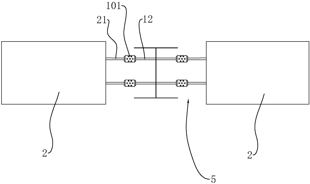
[0080] Step b, connecting the connecting steel bar 12 and the pre-embedded steel bar 21 to each other by welding or connecting with a sleeve 101;

[0081] Or penetrate the insertion rib 4 in the perforation 17, and weld the insertion rib 4 to the pre-embedded steel bar 21 or connect it with the sleeve 101;

[0082] Step c, install the ribs 51 and the stirrups 52 inside the post-casting belt 5, so that the sleeve 101 is surrounded by multiple ribs 51;

[0083] Step d, installing the post-casting tape 5 formwork;

[0084] When the concrete prefabricated wall panel 2 is an outer wall, paste the second thermal insulation laminate 8 between two adjacent first thermal insulation lamin...


PUM


Abstract

The invention discloses a connecting structure for prefabricated concrete wall panels and steel columns. The key point of the technical scheme is as follows: the connecting structure comprises sectionsteel columns and the prefabricated concrete wall panels, the section steel columns are vertically arranged, the prefabricated concrete wall panels are arranged in at least two directions of four side faces of each section steel column, and the prefabricated concrete wall panels and the section steel columns compose a straight, L-shaped, T-shaped or cross wall structure; post-cast strips are arranged between the section steel columns and the prefabricated concrete wall panels; connecting rebars which horizontally extend out are perpendicularly and fixedly connected to the four side faces of each section steel column, embedded rebars are arranged in the end surface, which is close to the section steel column, of each prefabricated concrete wall panel, part of each embedded rebar is locatedin a wall, and the other part extends into the post-cast strip; and after being fixedly connected, the connecting rebars and the embedded rebars are buried in concrete of the post-cast strips. The connecting structure ensures that the connection between the prefabricated concrete wall panels and the steel columns has good integrity and is steadier.

Description

technical field [0001] The invention relates to a wallboard connection structure in an assembled building, in particular to a connection structure between a concrete prefabricated wallboard and a steel column and a construction method thereof. Background technique [0002] During the installation process of concrete prefabricated wall panels in the process of building construction, metal materials such as steel plates or steel bars are often used on the concrete prefabricated wall panels to be welded or bolted to steel columns such as H-shaped steel to realize the fixed installation of concrete prefabricated wall panels. However, there is no connection between two adjacent concrete prefabricated wall panels, so that the connection nodes between the prefabricated panels and the steel structure have the disadvantages of poor integrity and poor earthquake resistance. Contents of the invention [0003] The purpose of the present invention is to provide a connection structure...

Claims


Application Information

Patent Timeline
Patent Type & Authority Applications(China)
IPC IPC(8): E04B2/60
CPCE04B2/60
Inventor 李藏柱
Owner 李藏柱
Why Eureka
Try Eureka