
Self-guiding gentle wind power generation equipment

A power generation equipment and self-guiding technology, applied in wind power generation, mechanical equipment, and wind turbines consistent with the wind direction, etc., can solve the problems of inability to ensure the air collection port, loss of wind energy, and utilization of wind energy, so as to increase the effect of wind collection, Effect of reducing energy loss and protecting power generation equipment

Pending Publication Date: 2018-08-21
HEBEI UNIV OF TECH +1
View PDF3 Cites 3 Cited by
  • Summary
  • Abstract
  • Description
  • Claims
  • Application Information

AI Technical Summary

Problems solved by technology

The disadvantages of this design are: 1. When the wind collected by the air collecting head passes through the curved air pipe and reaches the vertical air collecting cylinder, a large amount of wind energy will be lost; 2. It is impossible to ensure that the air collecting port is always in the windward direction
The disadvantage of this design is that when the wind direction is uncertain, the air inlet cannot always be directed towards the stronger wind direction, and the wind energy cannot be utilized to the greatest extent.

Method used


Image

  • Self-guiding gentle wind power generation equipment
  • Self-guiding gentle wind power generation equipment
  • Self-guiding gentle wind power generation equipment

Examples


Embodiment Construction

[0020] Specific examples of the present invention are given below. The specific embodiments are only used to further describe the present invention in detail, and do not limit the protection scope of the claims of the present application.

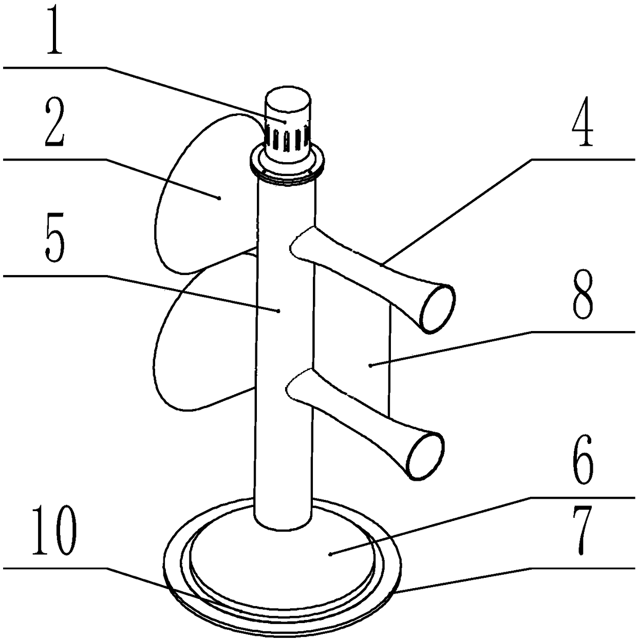
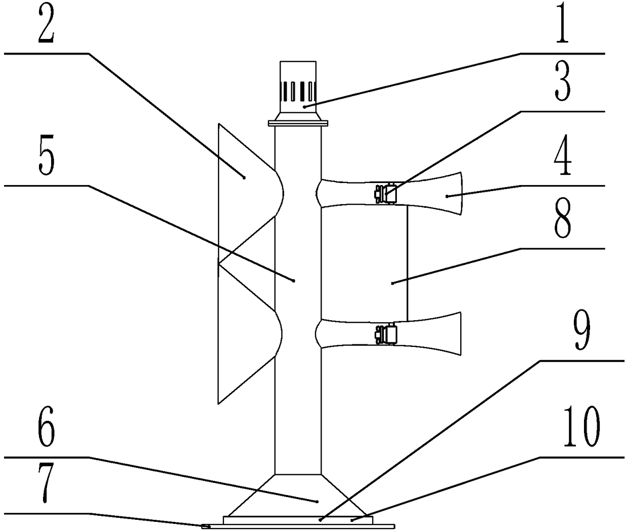
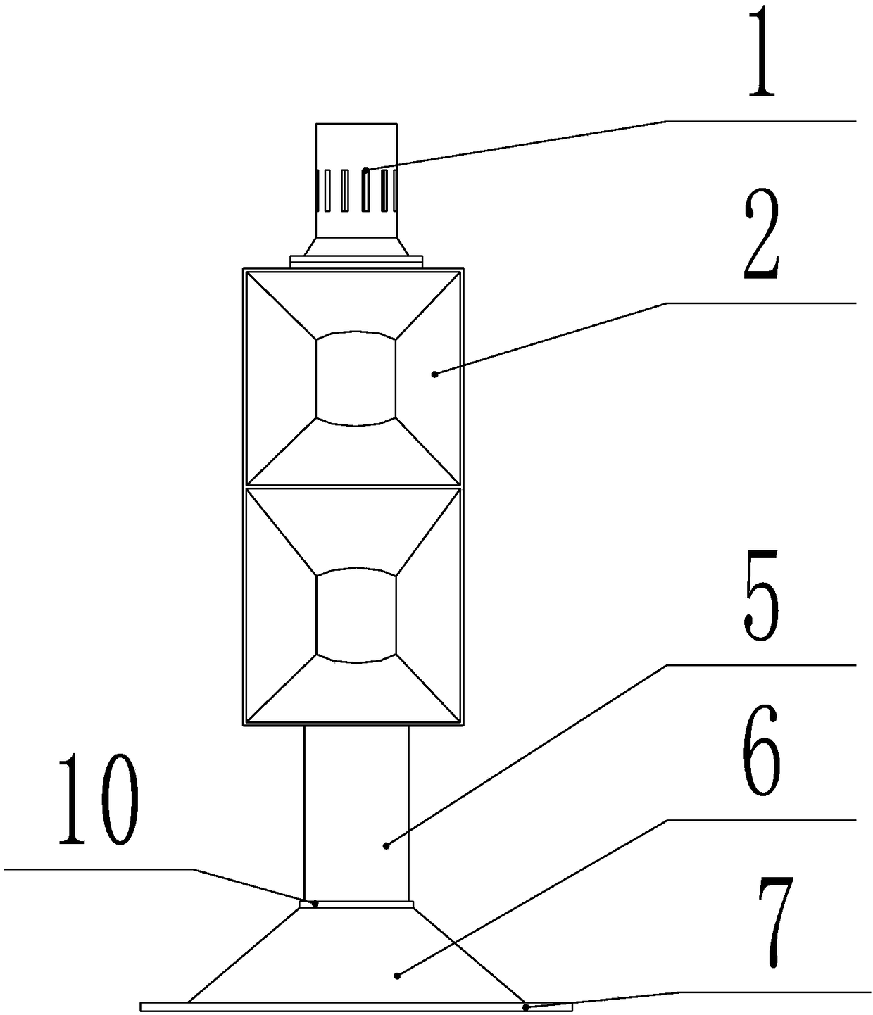
[0021] The invention provides a kind of self-guided breeze power generation equipment (see Figure 1-4 , referred to as equipment), is characterized in that the equipment includes a lightning protection device 1, a horn-shaped wind collector 2, a wind generator 3, an acceleration tube 4, a tubular tower 5, a boss 6, a base 7, a guide plate 8, a ball 9 and a ball plate 10;

[0022] The base 7 is circular and fixed on the ground; the boss 6 is circular and mounted on the base 7 for installing the tubular tower 5; the lower end of the tubular tower 5 is connected with the boss 6, and the tubular tower 5 A lightning protection device 1 with vents is installed on the top, and the lightning protection device 1 plays the role of reducing wind re...


PUM


Abstract

The invention discloses self-guiding gentle wind power generation equipment. The self-guiding gentle wind power generation equipment comprises a lightning arrester, horn-shaped wind collectors, wind power generators, acceleration pipes, a tubular tower, a lug boss, a pedestal, guide plates, a ball and a ball plate; the lower end of the tubular tower is connected with the lug boss; the lightning arrester provided with a ventilating opening is installed at the top end of the tubular tower; the tubular tower can rotate 360 degrees horizontally relative to the ground by virtue of the ball; the ball plate comprises a ball rail; at least two horn-shaped wind collectors are uniformly distributed on the tubular tower; the acceleration pipes are uniformly distributed on the tubular tower; the quantity of the acceleration pipes is the same as that of the horn-shaped wind collectors; one acceleration pipe correspondingly communicates with one horn-shaped wind collector; the central axes of each acceleration pipe and the corresponding horn-shaped wind collector are collinear; each acceleration pipe is of a structure of which the two ends are thick and the middle is gradually thinned; one end of each acceleration pipe is connected with the tubular tower; the size of a wind leaking opening of the other end of each acceleration pipe is smaller than the size of a wind collecting opening of thecorresponding horn-shaped wind collector; each wind power generator is installed at the thinnest position of the corresponding acceleration pipe, and each guide plate which is perpendicular to the horizontal plane is installed between the corresponding two adjacent acceleration pipes.

Description

technical field [0001] The invention relates to a wind energy generating device, in particular to a self-guided breeze generating equipment. Background technique [0002] With the shortage of traditional energy sources in the world, countries around the world are paying more and more attention to the utilization of various renewable and clean energy sources. There is no fuel problem in wind power generation, nor will it produce radiation and environmental pollution, and it is inexhaustible. The current wind power generation technology is relatively mature, using the wind to blow the wind blades to rotate, and convert the wind energy into mechanical energy to drive the power generation device to work, thereby generating available electric energy. Windmill-type power generation equipment is currently the most widely used, but it has high requirements on the material and strength of the blades, and it is difficult to maintain and protect. Windmill-type power generation equipm...

Claims


Application Information

Patent Timeline
Patent Type & Authority Applications(China)
IPC IPC(8): F03D1/04F03D9/25F03D7/04F03D13/20F03D80/00F03D80/30
CPCF03D1/04F03D7/0204F03D9/25F03D13/20F03D80/00F03D80/30Y02E10/728Y02E10/72
Inventor 关玉明曹颜楠张聪聪何川黄思硕韩晓耀李祥利苗艺男
Owner HEBEI UNIV OF TECH
Learn More