Heat pipe cooling device for sliding bearing of melt gear pump

A sliding bearing and cooling device technology, used in pumps, pump components, machines/engines, etc., can solve the problems of small coolant heat capacity, complicated sliding bearing design, poor cooling effect, etc.

Active Publication Date: 2018-08-21
日照市大华流体控制有限公司
View PDF6 Cites 2 Cited by
  • Summary
  • Abstract
  • Description
  • Claims
  • Application Information

AI Technical Summary

Problems solved by technology

In addition to the problem of coolant sealing, considering the strength of the sliding bearing, the radial dimension of the sliding bearing must be increased, which complicates the design of the sliding bearing
Due to the thickness of the sliding bearing itself and the small cavity, the heat capacity of the coolant is small, increasing the circulation speed to enhance cooling is limited, the cooling effect is not good, and the gain outweighs the gain

Method used


Image

  • Heat pipe cooling device for sliding bearing of melt gear pump
  • Heat pipe cooling device for sliding bearing of melt gear pump
  • Heat pipe cooling device for sliding bearing of melt gear pump

Examples


Embodiment 1

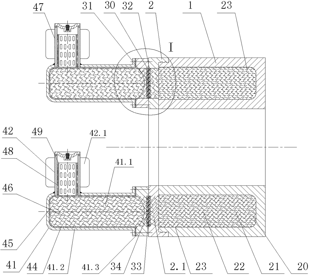
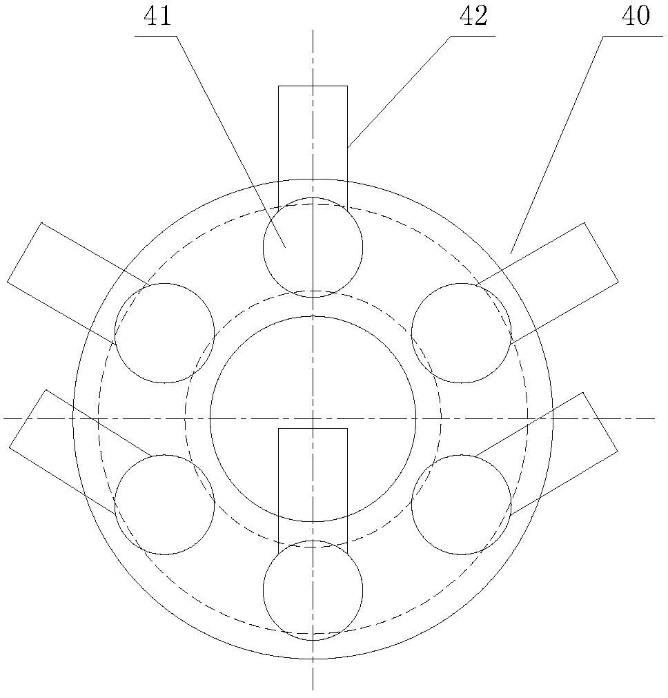
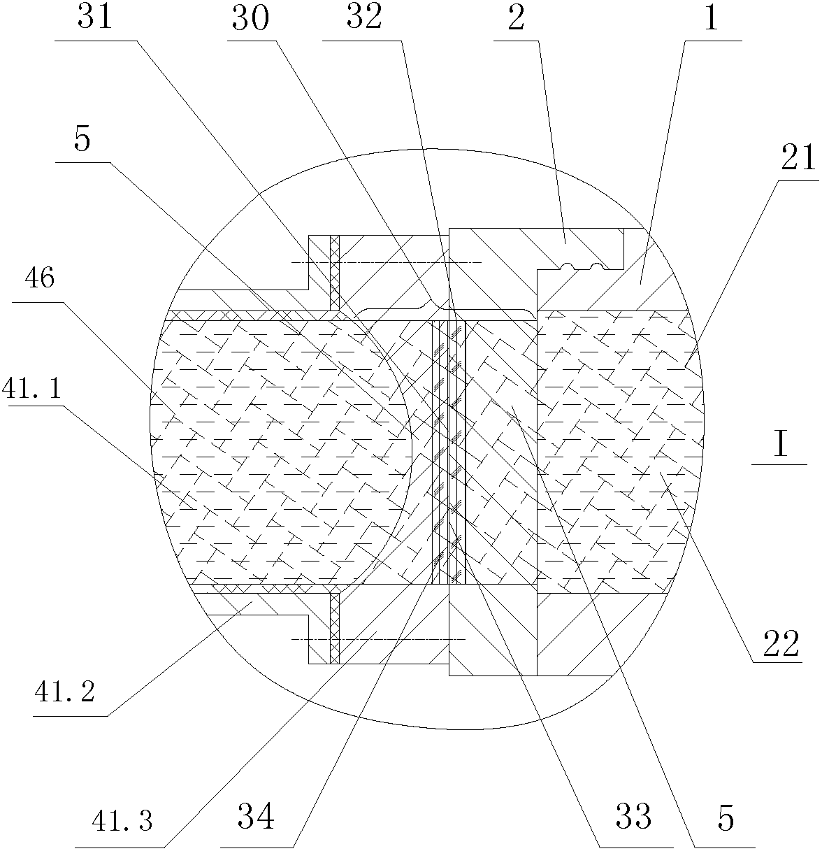
[0049] Such as Figure 1-4 As shown, a heat pipe cooling device for a melt gear pump sliding bearing includes a solid-liquid phase change heat storage structure 20, a thermal coupling structure 30, and a columnar heat pipe heat dissipation structure 40. The solid-liquid phase change heat storage structure 20 includes a heat storage foam metal The ring 21, the heat storage material 22, and the bearing cover 2 are axially sealed and fixed on the side of the sliding bearing body 1 to form an annular heat storage chamber 23, and the solid-liquid phase change heat storage structure 20 is arranged in the annular heat storage chamber 23. A plurality of heat pipe heat dissipation structures 40 are arranged outside the bearing cover 2 , and the solid-liquid phase change heat storage structure 20 is connected to the heat pipe heat dissipation structures 40 through a thermal coupling structure 30 .

[0050] The heat pipe heat dissipation structure 40 includes an evaporation part 41 and a...

Embodiment 2

[0056] In order to increase the heat dissipation capability of the heat pipe heat dissipation structure 40, the thermal coupling structure 30 is improved.

[0057] Such as Figure 5-7 As shown, a heat pipe cooling device for a melt gear pump sliding bearing includes a solid-liquid phase change heat storage structure 20, a thermal coupling structure 30, and a heat pipe cooling structure 400. The sliding bearing includes a sliding bearing body 1, and the sliding bearing body 1 is provided with an annular Cavity 3 , a pair of Hough rings 4 are embedded in the annular cavity 3 to form a closed annular heat storage cavity 23 . The solid-liquid phase change heat storage structure 20 includes a heat storage foam metal ring 21 and a heat storage material 22 , and the solid-liquid phase change heat storage structure 20 is arranged in an annular heat storage cavity 23 . The heat storage metal foam ring 21 is made up of a pair of half-rings of Hough type. The solid-liquid phase change ...


PUM

PropertyMeasurementUnit
Average life expectancyaaaaaaaaaa

Abstract

A heat pipe cooling device for a sliding bearing of a melt gear pump comprises solid-liquid phase-change heat storage structures, heat coupling structures and at least 6 heat pipe heat-dissipating structures, wherein the solid-liquid phase-change heat storage structures are connected with the heat pipe heat-dissipating structures through the heat coupling structures; ring-shaped heat storage cavities are arranged in a sliding bearing body; the solid-liquid phase-change heat storage structures are arranged in the ring-shaped heat storage cavities, and comprise heat storage foam metal rings andheat storage materials; the heat pipe heat-dissipating structures are circumferentially arranged at intervals on the axial end surface of the sliding bearing body; heat pipe foam metal is arranged inthe heat pipe heat-dissipating structures; and the heat coupling structures are arranged between the heat pipe heat-dissipating structures and the sliding bearing body. Through the interaction among the above structures in three aspects, the common purpose of dissipating heat of the sliding bearing in time and prolonging the service life of the melt gear pump is fulfilled.

Description

technical field [0001] The invention relates to the technical field of a melt gear pump, in particular to a heat pipe cooling device for a melt gear pump sliding bearing heat pipe. Background technique [0002] The shaft of a pair of meshing gears that transport high-temperature melt in the melt gear pump rotates at high speed for a long time, and the gear shaft uses sliding bearings in the pump body. There is an integral radial sliding bearing at both ends of the long and short shafts, and the four bearings act as bearings and baffles to prevent the melt flow and the movement of the gear shaft. The sliding bearing must work continuously under the condition of high temperature below 350°C and high pressure of about 30MPa. The sliding bearing of the gear pump belongs to the hydrodynamic pressure bearing, and the lubrication of the bearing is realized by the melt medium itself flowing from the high pressure side through the bearing oil tank . The main reason for the failure ...

Claims


Application Information

Patent Timeline
IPC IPC(8): F04C15/00F04C13/00
CPCF04C13/002F04C15/0096F04C2240/50
Inventor 许梦艳
Owner 日照市大华流体控制有限公司
Why Eureka
Try Eureka