Fiber coating removal device, removal system, removal method and external device

A technology of external devices and optical fibers, applied in the directions of light guides, optics, optical components, etc., can solve the problems of increasing the frequency of changing heating conditions and increasing the trouble, and achieve the effect of easy setting and changing operations.

Active Publication Date: 2020-12-25
THE FUJIKURA CABLE WORKS LTD
View PDF9 Cites 0 Cited by
  • Summary
  • Abstract
  • Description
  • Claims
  • Application Information

AI Technical Summary

Problems solved by technology

However, the diversification of optical fibers as described above increases the frequency of setting and changing of heating conditions during splicing work, and the work of changing the setting and changing of coating heating conditions becomes more troublesome.

Method used


Image

  • Fiber coating removal device, removal system, removal method and external device
  • Fiber coating removal device, removal system, removal method and external device
  • Fiber coating removal device, removal system, removal method and external device

Examples


no. 1 approach

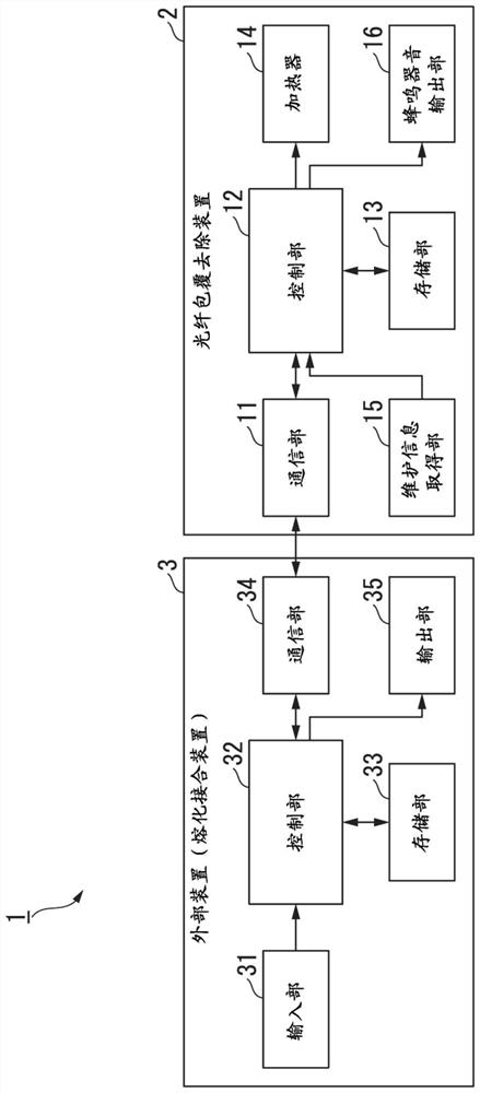
[0059] Hereinafter, an optical fiber coating removal system according to a first embodiment of the present invention will be described with reference to the drawings.

[0060] Such as figure 1 as well as figure 2 As shown, the optical fiber coating removal system 1 of the present embodiment includes an optical fiber coating removal device 2 (hereinafter, simply referred to as the coating removal device 2 ) and an external device 3 .

[0061] Such as figure 1 As shown, the coating removal device 2 includes a communication unit 11 , a control unit 12 , a storage unit 13 , a heater 14 , a maintenance information acquisition unit 15 , and a buzzer sound output unit 16 . In addition, the external device 3 is an optical fiber fusion splicing device (hereinafter, simply referred to as a fusion splicing device) that melts and splices optical fibers from which the coating at the ends has been removed. Hereinafter, the present embodiment will be described with the external device 3 ...

no. 2 approach

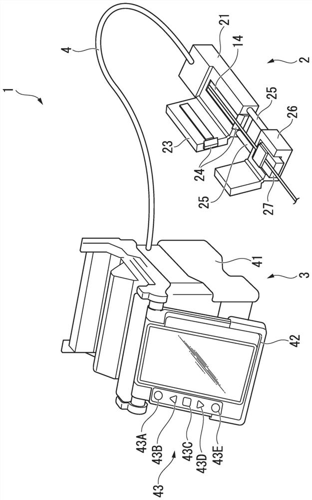
[0166] Next, an optical fiber coating removal system according to a second embodiment of the present invention will be described with reference to the drawings. The main difference replaced by the optical fiber coating removal system of the second embodiment is that the optical fiber coating removal system of the first embodiment is no longer a fusion splicing device, but a mobile terminal. In addition, the coating removal device 2 differs from the above-mentioned embodiment mainly in the information stored in the storage unit 13 and the control by the control unit 12 compared with the coating removal device 2 of the first embodiment. Hereinafter, the second embodiment will be described focusing on differences from the above-described embodiment. In addition, the same code|symbol is attached|subjected to the common member and element in some cases, and the description is abbreviate|omitted.

[0167] Such as Figure 21 As shown, the optical fiber coating removal system 5 incl...


PUM

PropertyMeasurementUnit
thicknessaaaaaaaaaa
thicknessaaaaaaaaaa

Abstract

An optical fiber coating removal device, a removal system, a removal method, and an external device. The optical fiber coating removal device that heats the coating of an optical fiber with a heater and removes the coating of the optical fiber with a knife includes: a communication unit that receives information based on fiber type information from an external device that specifies the type of fiber selected from a plurality of fiber types by the user, and input to the external device; and a heater that uses the received The cladding heating of the optical fiber is performed based on the information of the optical fiber type information, and the heater can perform cladding heating under a plurality of conditions corresponding to the optical fiber type information.

Description

technical field [0001] The invention relates to an optical fiber coating removal device, a removal system, a removal method and an external device. [0002] This application claims priority based on Japanese Patent Application No. 2017-025329 filed in Japan on February 14, 2017, and uses the content here. Background technique [0003] In order to splice the optical fibers, there is an optical fiber coating removal device that removes the coating of the terminal portion of each optical fiber. An optical fiber coating removal device includes a heater for heating the coating of an optical fiber (for example, refer to Patent Documents 1 and 2). [0004] Such an optical fiber coating removal device cuts into the coating of the optical fiber, heats and softens the coating of the removed terminal portion with a heater, and removes the softened coating to remove the coating of the optical fiber. [0005] Patent Document 1: Japanese Patent Application Publication No. 1-90003 [00...

Claims


Application Information

Patent Timeline
Patent Type & Authority Patents(China)
IPC IPC(8): G02B6/245
CPCG02B6/245G02B6/2553G02B6/566Y10S156/923Y10T156/1911Y10T156/1153Y10T156/1184Y10T156/1967
Inventor 川西纪行
Owner THE FUJIKURA CABLE WORKS LTD
Why Eureka
Try Eureka