
Iron-chromium flow battery

A technology of flow battery and chromium solution, applied in the field of iron-chromium flow battery, can solve the problems of large degree of side reaction, and the performance and capacity of flow battery are not particularly good, and achieve the effect of improving performance and capacity

Inactive Publication Date: 2018-08-21
杜克兰
View PDF4 Cites 7 Cited by
  • Summary
  • Abstract
  • Description
  • Claims
  • Application Information

AI Technical Summary

Problems solved by technology

However, the carbon paper flow battery uses carbon paper made of carbon fiber material as the electrode material, which has a large degree of side reactions, and the performance and capacity of the flow battery are not particularly good.

Method used


Image

  • Iron-chromium flow battery
  • Iron-chromium flow battery
  • Iron-chromium flow battery

Examples


Embodiment Construction

[0021] It should be noted that, in the case of no conflict, the embodiments of the present invention and the features in the embodiments can be combined with each other. The present invention will be described in detail below with reference to the accompanying drawings and examples.

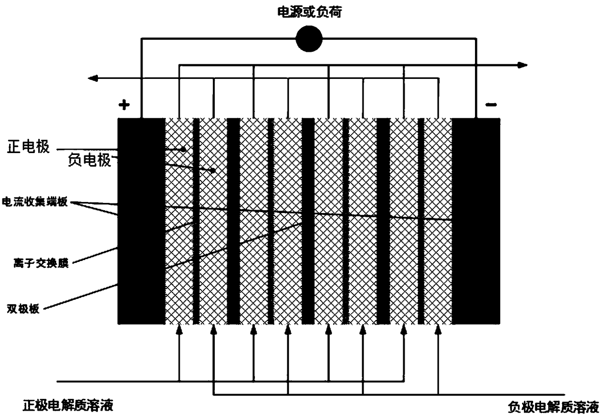
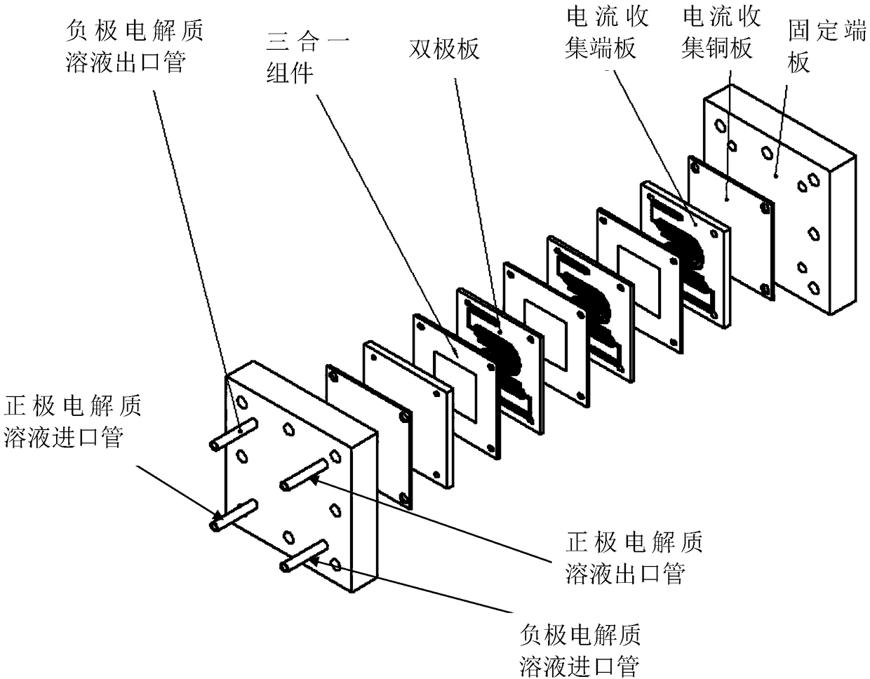
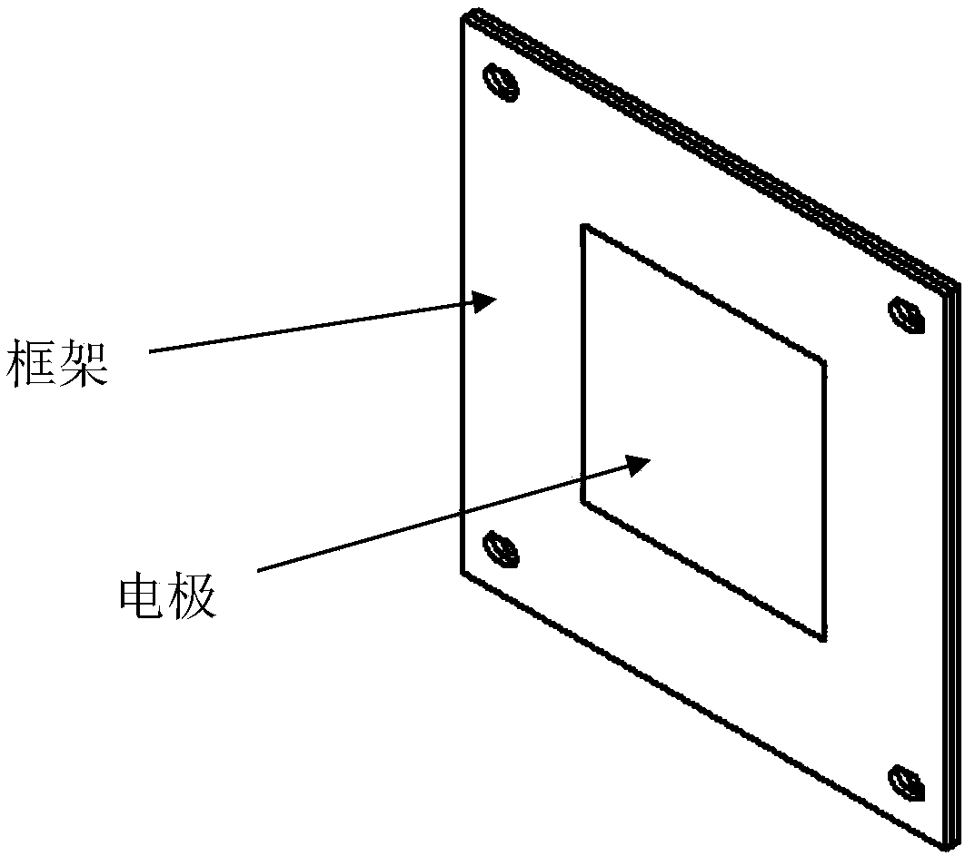
[0022] Such as Figures 1 to 5 As shown, the present invention preferably prefers an iron-chromium flow battery, such as figure 2 As shown, the iron-chromium flow battery includes a three-in-one component, a current collecting end plate, a bipolar plate, a current collecting copper plate, and a fixed end plate. The bipolar plate is sandwiched between the three-in-one component, and the three-in-one The component is attached with a current collecting end plate, and the fixed end plate is located at both ends of the iron-chromium flow battery to fix the three-in-one component, the current collecting end plate, the bipolar plate, and the current collecting copper plate, and the current collecting ...


PUM

PropertyMeasurementUnit
Tensile modulus of elasticityaaaaaaaaaa
Thicknessaaaaaaaaaa
Areaaaaaaaaaaa

Abstract

The invention discloses an iron-chromium flow battery. The iron-chromium flow battery comprises positive electrodes, negative electrodes, diaphragms, current collecting end plates and electrolyte solutions, wherein each positive electrode and the corresponding negative electrode are located on the left and right sides of each diaphragm; the positive electrodes, the negative electrodes and the diaphragms are located between the current collecting end plates at left and right ends; the electrolyte solutions are located in positive electrode cavities and negative electrode cavities; and at leastone of positive electrode and negative electrode materials is mainly made of a carbon paper material prepared from graphite fiber. The electrode materials are mainly made of the carbon paper materialprepared from the graphite fiber, and the performance and the capability of the iron-chromium flow battery are improved.

Description

technical field [0001] The invention relates to the field of new energy, in particular to an iron-chromium flow battery. Background technique [0002] As early as the 1970s and 1980s, the Lewis Research Center of NASA (Lewis Research Center) invested a lot of research on the iron-chromium (Fe / Cr) battery system, overcoming the electrolyte solution of the positive and negative electrodes. Through the mixing problem of the electrolyte membrane and the preparation of the key components of the catalytic electrode, a 1kW battery energy storage system has been developed, and the efficiency of the battery is still above 80% after 100 charge-discharge cycles. Afterwards, the technology property rights were transferred to commercial companies to prepare for product development, but due to the slowdown of the oil crisis, the company did not choose to further develop this technology. In the late 1980s, Japan's Sumitomo Corporation Shimokansai Electric Power Company reported that a 10k...

Claims


Application Information

Patent Timeline
IPC IPC(8): H01M4/86H01M8/0234H01M8/0263H01M8/18
CPCH01M4/8605H01M8/0234H01M8/0263H01M8/188Y02E60/50
Inventor 杜克兰
Owner 杜克兰
Learn More