Motor self-driven cooling structure based on cooling liquid

A cooling structure and cooling liquid technology, applied in the direction of electric components, cooling/ventilation devices, magnetic circuit shape/style/structure, etc., can solve the problems of inability to cool the stator and rotor, and low heat dissipation efficiency of the motor cooling structure, so as to increase the use efficiency , reduce cost, reduce the effect of cooling structure

Pending Publication Date: 2018-08-21
GUANGDONG SHANGSHUI ENERGY TECH
View PDF18 Cites 3 Cited by
  • Summary
  • Abstract
  • Description
  • Claims
  • Application Information

AI Technical Summary

Problems solved by technology

[0007] In view of this, the purpose of the present invention is to overcome the deficiencies of the prior art, to provide a motor self-driven cooling structure based on coolant, with independent stator cooling system and rotor cooling system, to solve the heat dissipation efficiency of the existing motor cooling structure Low, unable to cool the stator and rotor separately, etc.

Method used


Image

  • Motor self-driven cooling structure based on cooling liquid
  • Motor self-driven cooling structure based on cooling liquid

Examples


Embodiment Construction

[0037] The following will clearly and completely describe the technical solutions in the embodiments of the present invention with reference to the accompanying drawings in the embodiments of the present invention. Obviously, the described embodiments are only some, not all, embodiments of the present invention. Based on the embodiments of the present invention, all other embodiments obtained by persons of ordinary skill in the art without making creative efforts belong to the protection scope of the present invention.

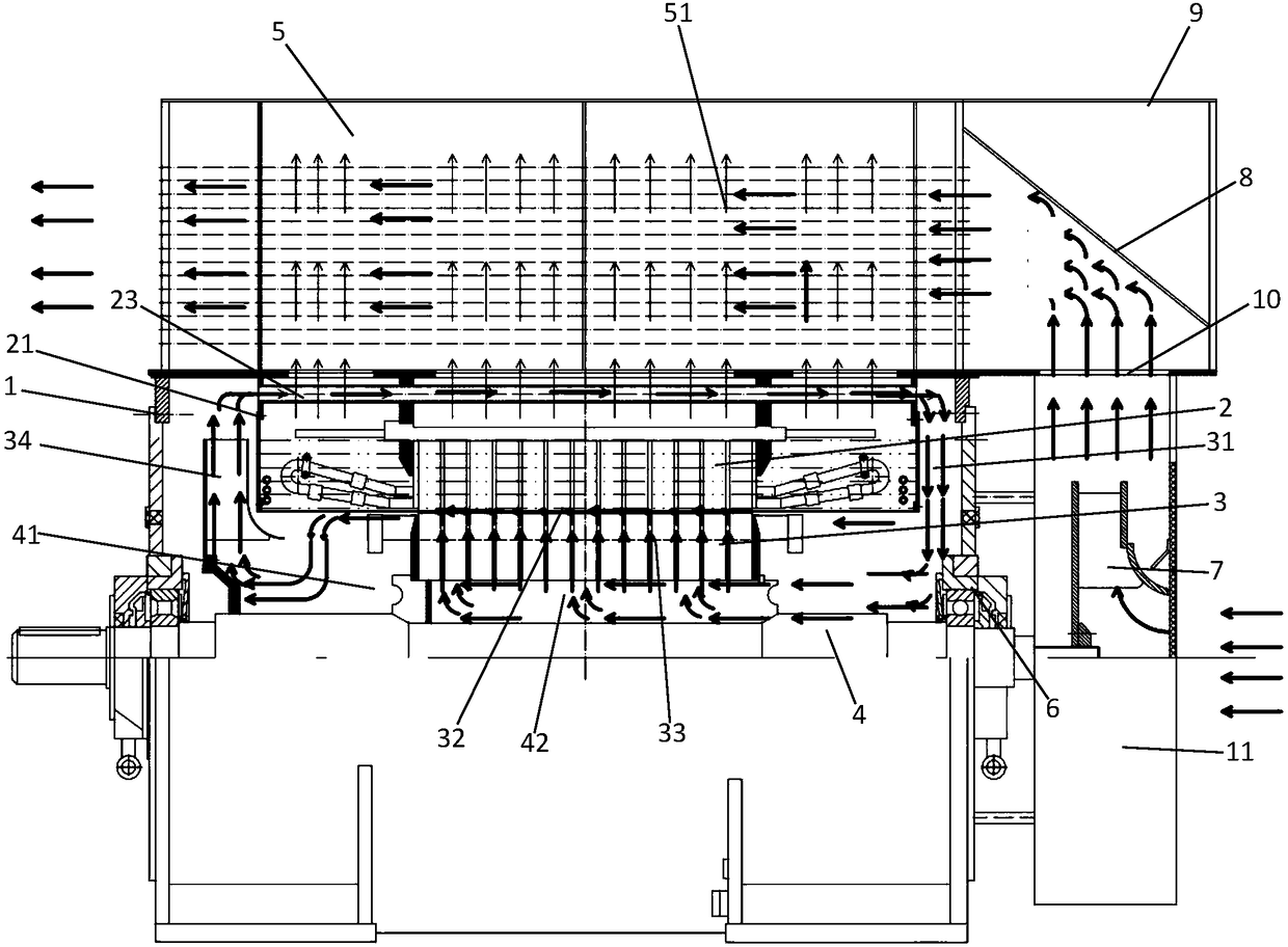
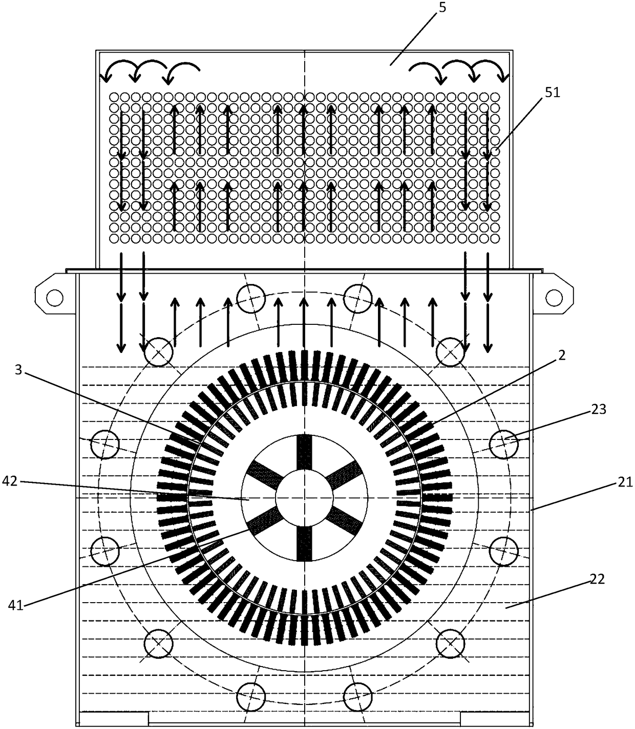
[0038] The motor includes a casing 1, a stator core 2 fixed in the casing 1 through a frame, a rotor core 3 penetrating into the inner cavity of the stator core 2, the stator core 2 is aligned with the rotor core 3, and the rotor core 3 is socketed In the middle of the rotating shaft 4, it also includes a sealing cover 21, a ventilation pipe 23, a cooling liquid pool, an inner fan 34 and a cooler 5; the cooler 5 is installed on the top of the casing 1; Driven ...


PUM


Abstract

The invention discloses a motor self-driven cooling structure based on cooling liquid. A cooler is installed at the top of a shell; a shaft-driven outer fan is driven by a rotary shaft to rotate coaxial to the rotary shaft; a sealing hood penetrates through the inner diameter of a stator iron core and extends into the cooler, and is isolated from the space of a rotor iron core in the shell to forma closed space; the cooling liquid is injected into the sealing hood; vent pipes are located at the axial outer side of the stator iron core, and the two ends of each vent pipe are communicated withthe space of the rotor iron core; several subplates are connected between the rotary shaft and the rotor iron core, and iron core axial ducts are formed by the spaces among the subplates; an air gap is formed between the rotor core and the inner circumferential face of the sealing hood; an inner fan is used for generating power airflow in a rotor circulating air path composed of the space of the rotor iron core, the vent pipes, the iron core axial ducts, rotor iron core radial ducts and the air gap. The motor self-driven cooling structure has a stator cooling loop and a rotor cooling loop which are independent from each other, but both the stator cooling loop and the rotor cooling loop absorb heat through the cooling liquid, the using efficiency of the cooling liquid is improved, the costis lowered, and the cooling efficiency is improved.

Description

technical field [0001] The invention relates to the technical field of motors, in particular to a cooling liquid-based self-driven cooling structure for motors. Background technique [0002] The motors used in the society now usually encounter the problem of motor heating, which is a major problem in the industry. Generally, the purpose of cooling is achieved by increasing materials and reducing motor capacity. It will directly cause the amount of copper and iron to be used far beyond the ordinary motor with the same capacity. Such copper loss and iron loss are also higher than those of motors of the same type. How to solve this difficult problem in the industry, reduce the material and increase efficiency of ordinary motors, and make the self-driven cooling structure of high-tech motors based on coolant cool down and run smoothly has become the primary issue. [0003] In addition to changing the motor material and structure to achieve the purpose of cooling, the cooling ...

Claims


Application Information

Patent Timeline
Patent Type & Authority Applications(China)
IPC IPC(8): H02K9/197H02K1/32H02K9/20H02K9/08
CPCH02K1/32H02K9/08H02K9/197H02K9/20
Inventor 杨华
Owner GUANGDONG SHANGSHUI ENERGY TECH
Why Eureka
Try Eureka