Granary capable of dehumidifying and dissipating heat

A granary and grain storage technology, applied in the dehumidification and heat dissipation granary field, can solve the problems of uneven dehumidification and low dehumidification efficiency, and achieve the effect of accelerating the diffusion speed, improving efficiency and extending the maintenance cycle

Inactive Publication Date: 2018-08-24
ZHENGZHOU LONGWEI ELECTRONICS TECH CO LTD
View PDF0 Cites 4 Cited by
  • Summary
  • Abstract
  • Description
  • Claims
  • Application Information

AI Technical Summary

Problems solved by technology

[0004] In view of this, this application provides a granary capable of dehumidification and heat dissipation, which solves the problems of uneven dehumidification and low dehumidifi

Method used


Image

  • Granary capable of dehumidifying and dissipating heat

Examples


Embodiment 1

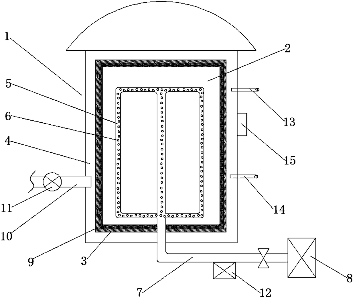
[0017] Such as figure 1 A granary that can dehumidify and dissipate heat is shown, the granary 1 is provided with a grain storage cavity 2, and the cavity wall 3 of the grain storage cavity 2 is a mesh structure, and the mesh size of the mesh structure is not larger than the particle size of the grain , a gas passage 4 is formed between the grain storage chamber 2 and the inner wall of the granary 1, and an exhaust device communicating with the outside of the granary 1 is connected to the gas passage 4, and a plurality of Parallel dehumidification pipeline 5, said dehumidification pipeline 5 evenly has a plurality of through-holes 6, and a plurality of said dehumidification pipelines 5 are all connected with the intake main pipe 7, and said intake main pipe 7 extends to the outside of the granary 1, and connects with the granary 1 external inert gas installation 8 connection.

[0018] In the above-mentioned embodiment, a dehumidification pipeline 5 is arranged inside the grai...

Embodiment 2

[0020] Based on Example 1, such as figure 1 As shown, the inner wall of the grain storage cavity 2 is also provided with a filter cloth 9, and the aperture of the filter cloth 9 is not larger than the mesh size of the mesh structure. By setting the filter cloth 9 on the inner wall of the grain storage cavity 2, dust impurities in the grain are prevented from entering the gas passage 4, causing accumulation of dust in the gas passage 4, improving the life of the equipment, and prolonging the maintenance cycle.

Embodiment 3

[0022] Based on Example 1, such as figure 1 As shown, the exhaust device includes an exhaust pipe 10 communicated with the gas channel 4 , and an induced draft fan 11 is arranged on the exhaust pipe 10 . Through the arrangement of the induced draft fan 11, the diffusion speed of the gas can be accelerated, and the efficiency of dehumidification and heat dissipation can be further improved.


PUM


Abstract

The invention provides a granary capable of dehumidifying and dissipating heat. According to the invention, the interior of the granary is provided with a grain storage chamber; the chamber wall of the grain storage chamber has a mesh structure; the mesh size of the mesh structure is no larger than the particle size of a grain; a gas channel is formed between the grain storage chamber and the inner wall of the granary; an exhaust device communicating with the exterior of the granary is connected with and arranged on the gas channel; a plurality of dehumidification pipelines in parallel connection are uniformly distributed in the interior of the grain storage chamber; each dehumidification pipeline is uniformly provided with a plurality of through holes; and the plurality of the dehumidification pipelines are connected with a gas inlet main pipe which extends to the exterior of the granary and is connected with an inert gas device arranged at the exterior of the granary. The granary provided by the invention solves the problems of non-uniform dehumidification and low dehumidification efficiency due to the presence of moisture gradients in the conventional grain dehumidification process, can quickly and uniformly dehumidify, and dissipates heat with high efficiency at the same time.

Description

technical field [0001] The invention relates to the technical field of grain storage equipment, in particular to a granary capable of dehumidification and heat dissipation. Background technique [0002] Grain is an important material for the national economy and the people's livelihood. The moisture contained in the grain needs to be dried to the required humidity value before it can be stored safely. When the dried grain is stored in the granary, the humidity in the granary will increase due to the long storage time and weather changes. If the granary is not dried in time, the humidity in the granary will drop. It will make the grain mildew and cause the grain to deteriorate. Even if the grain storage with low water content is poor, if the ventilation effect of the granary is not good, the storage time will affect the storage quality of the grain. [0003] Grain drying is a process with high energy consumption. Coal is usually used as fuel for drying high-moisture grains. ...

Claims


Application Information

Patent Timeline
IPC IPC(8): A01F25/14A01F25/22
CPCA01F25/14A01F25/22
Inventor 赵峰
Owner ZHENGZHOU LONGWEI ELECTRONICS TECH CO LTD
Why Eureka
Try Eureka