
Efficient magnetic grading machine

A classifier and magnetic technology, which is applied in the field of high-efficiency magnetic classifiers, can solve the problems of low screening efficiency, large medium ore circulation, and reduced continuous body grinding efficiency, so as to reduce the number of beneficiation equipment segments, improve economic benefits, The effect of reducing the cost of concentrate

Pending Publication Date: 2018-08-24
刘阳
View PDF0 Cites 2 Cited by
  • Summary
  • Abstract
  • Description
  • Claims
  • Application Information

AI Technical Summary

Problems solved by technology

[0010] Various screening and grading equipment classified according to particle size, due to the small size of the sieve hole, generally 0.1mm to 0.2mm, the sieving efficiency is not high, and the product on the sieve contains a large number of particles smaller than the sieve size, many of which are The magnetite particles that have been dissociated from the monomer returned to the ball mill for regrinding, but failed to enter the sieve, and thus did not enter the sorting operation
[0011] The grit or sieve products of the above two grading equipments contain a large amount of magnetite that has been dissociated from the monomer, because they return to the ball mill for regrinding, which not only causes the overgrinding of the monomer magnetite, but also causes the middle ore The vicious circle phenomenon of too much circulation reduces the grinding efficiency of the continuous body that really needs to be reground, and reduces the ability of the ball mill to process new ore

Method used


Image

  • Efficient magnetic grading machine
  • Efficient magnetic grading machine

Examples


Embodiment Construction

[0031] The present invention will be further described below in conjunction with accompanying drawing.

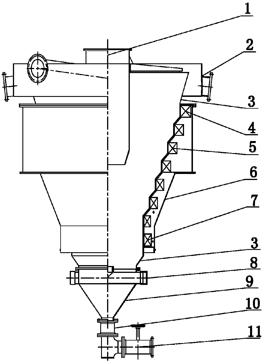
[0032] Such as figure 1 As shown, a high-efficiency magnetic classifier of the present invention includes an ore feeding tube 2, an ore feeding pipe 1 arranged on the ore feeding tube 2 along a tangential direction, a grading tube arranged on the outside of the ore feeding tube 2 and a grading tube arranged on the grading tube The upper overflow tank 3 is characterized in that the grading cylinder is a multi-diameter grading cylinder 4, and the grading cylinder 4 has 4 to 8 diameter reductions from top to bottom, and the total diameter reduction ratio is 1.5 to 2.0. And the minimum diameter is greater than the diameter of the ore feeding cylinder 2; on the outside of the multi-diameter grading cylinder 4, several excitation coils 5 are concentrically set from top to bottom, and a closed outer cylinder 6 is arranged on the outside of several excitation coils 5. The outside ...


PUM


Abstract

The invention relates to an efficient magnetic grading machine. The machine comprises an ore feeding barrel, an ore feeding barrel which is arranged on the ore feeding barrel in the tangent line direction, a grading barrel which is arranged at the outer side of the ore feeding barrel, and an overflowing groove which is formed in the upper part of the grading barrel. The machine is characterized inthat the grading barrel is a variable-diameter grading barrel; a plurality of exciting coils concentrically sleeve the outer side of the variable-diameter grading barrel from top to bottom; a closedouter barrel is arranged at the outer sides of the plurality of exciting coils; a water feeding pipe is arranged at the outer side of the lower part of the variable-diameter grading barrel in the tangent line direction; an inverted tapered barrel shaped bottom cone is mounted at the lower part of the variable-diameter grading barrel; a concentration sensor is mounted at the lower part of the bottom cone; and an electric ore discharging valve is mounted at the lower part of the concentration sensor. The machine has the advantages that the structure is simple; the grading efficiency is high; fine sieve based grading work is replaced; the quantity of sections of dressing equipment is decreased; the quantity of regrinding mills is decreased by two-thirds by being compared with the original quantity of the regrinding mills; the energy is saved; the consumption is decreased; the concentrate cost is greatly decreased; and as a result, the economic benefit of a dressing plant is increased.

Description

technical field [0001] The invention belongs to the technical field of hydraulic classification equipment, and in particular relates to a high-efficiency magnetic classification machine used for classification of magnetite in mineral processing plants. Background technique [0002] At present, the grading equipment used in the production process of the magnetite concentrator can be divided into two types according to the grading principle: the first one is in the composite force field of gravity or gravity and centrifugal force, according to the different settling speeds of particles in the fluid And the grading equipment for grading; the second is the sieving and grading equipment for grading according to the particle size. [0003] Equipment classified by gravity or a composite force field of gravity and centrifugal force includes: spiral classifiers, hydrocyclones, conical classifiers and trough classifiers. For these gravity-graded equipment, the settled products are sa...

Claims


Application Information

Patent Timeline
IPC IPC(8): B03C1/24
CPCB03C1/24
Inventor 刘阳刘秉裕
Owner 刘阳
Learn More