Oversampling DA converter

An analog-to-analog converter and over-sampling technology, which is applied in the field of over-sampled digital/analog converters, achieves the effects of reducing the number of segments, good precision, and realizing circuit miniaturization

Inactive Publication Date: 2003-11-19
PANASONIC CORP
View PDF2 Cites 0 Cited by
  • Summary
  • Abstract
  • Description
  • Claims
  • Application Information

AI Technical Summary

Problems solved by technology

[0026] In the above description, the worst case where a delay occurs at the most significant bit is shown. Even if the delay amount is adjusted appropriately, the Figure 18 The above-mentioned "flicker signal" problem basically occurs in the D / A converter of the decoder circuit shown

Method used


Image

  • Oversampling DA converter
  • Oversampling DA converter
  • Oversampling DA converter

Examples


no. 1 example

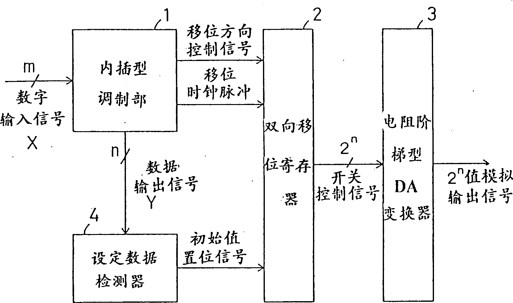
[0059] figure 1 An embodiment of the oversampled digital-to-analog converter of the present invention is shown. This figure is an example of the structure when interpolation type modulation is performed on the oversampled digital input signal, and a voltage divider type D / A conversion is performed on the low-bit digital output signal.

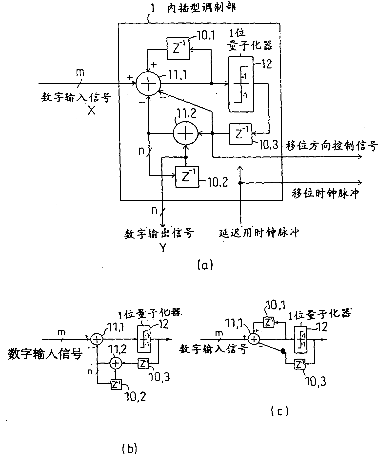
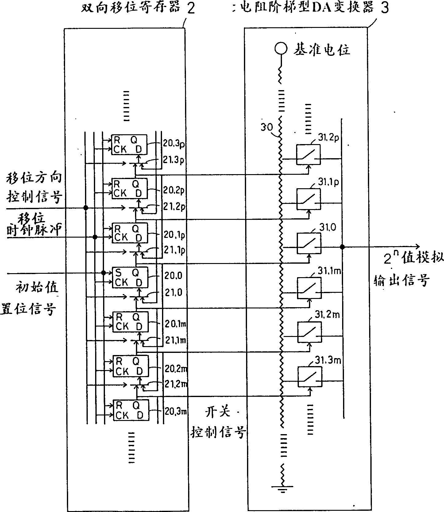
[0060] exist figure 1 Among them, 1 is the interpolation type modulation part (signal output part), 2 is the double shift register, 3 is the resistance ladder type D / A converter (resistor ladder type D / A converter), 4 is the setting data detection device. The above-mentioned interpolation modulator 1 has the same structure as that described in the above-mentioned prior art example, and performs interpolation modulation on the oversampled m-bit digital input signal, and outputs a low-bit n-bit digital signal. The converted n-bit digital output signal is sent to the set data detector 4, and the output (coincidence detection signal) of the se...

no. 2 example

[0090] Figure 8A second embodiment of the present invention is shown. The overall structure of this embodiment is the same as that of the above-mentioned first embodiment, and the difference lies in the internal structure of the interpolation type modulator. In the above-mentioned interpolation type modulator 1 of the first embodiment, the 1-bit quantizer 12 binarizes the output of the adder 11.1 into "+1" or "-1", while in the interpolation type modulator of the present embodiment 1', as shown in FIG. 9, differs from the prior art in that the 2-bit quantizer 12' triples the output of the adder 11.1 into "+1", "0" or "-1".

[0091] In the interpolation type modulator 1' shown in Fig. 9, the system function Y(Z) is expressed by the following formula:

[0092] Y(Z)=X(Z)+(1-Z -1 )*(1 / 2)*Q(Z)…(2)

[0093] That is, in the interpolation type modulator 1' of FIG. 9, the above-mentioned figure 1 Compared with the system function Y(Z) represented by the above formula (1) of the ...


PUM


Abstract

In an interpolative modulator, a signal which varies by only + / -1 with one clock from a 1-bit quantizer is used as a shift-direction control signal. The shift-direction control signal is given to a bidirectional shift register. The bidirectional shift register shifts data based on the value of the shift-direction control signal that has been received. The output from the bidirectional shift register is given as a control signal to a resistive-ladder-type D / A converter. The resistive-ladder-type D / A converter outputs an analog potential corresponding to a switch selected by the above control signal. Therefore, if a delay difference occurs between any two bits, two adjacent switches are simply selected simultaneously, so that the output from the resistive-ladder-type D / A converter varies continuously. Consequently, there can be provided an oversampling D / A converter of resistive-ladder type with high accuracy and an increased yield, which is free from glitch (transiently generated noise).

Description

technical field [0001] The invention relates to an over-sampling digital / analog converter for converting digital signals into analog signals, and particularly relates to the improvement of digital / analog conversion precision, low power consumption and yield. Background technique [0002] In recent years, with the miniaturization of semiconductor process technology, attention has been paid to oversampling type D / A converters as conversion means from digital signals to analog signals. The oversampling digital-to-analog converter is a sampling rate that converts the sampling rate of the input signal into a sampling rate that is ten to hundreds of times the frequency band of the input signal, and can drive the quantization noise to the high frequency side, so although it is faster than the input digital signal It is a digital / analog conversion method that can obtain a high-resolution analog output signal even with a low-level output signal. [0003] Known modulation methods use...

Claims


Application Information

Patent Timeline
Patent Type & Authority Patents(China)
IPC IPC(8): H03M3/04
CPCH03M3/376H03M3/50
Inventor 崎山史朗道正志郎丸山征克林锭二稻垣诚三松泽昭
Owner PANASONIC CORP
Why Eureka
Try Eureka