Efficient ultrasonic cleaning machine

A technology of ultrasonic waves and cleaning machines, applied in cleaning methods and appliances, cleaning methods using liquids, chemical instruments and methods, etc., can solve problems such as poor tolerance of cleaning parts, poor heating uniformity, and affecting cleaning effects, etc., to avoid The effect of cleaning dead corners, increasing the size range, and improving the cleaning effect

Inactive Publication Date: 2018-08-24
苏州布莱尔仪器有限公司
View PDF0 Cites 3 Cited by
  • Summary
  • Abstract
  • Description
  • Claims
  • Application Information

AI Technical Summary

Problems solved by technology

[0003] The heating device of the existing ultrasonic cleaning machine is usually installed on one side of the cleaning tank to heat the liquid in the entire cleaning tank. Not only is the heating uniformity poor, but once the temperature sensor detects that the temperature of the cleaning liquid exceeds the set value, it will stop heating. Because the heating temperature will have a period of inertial increase, usually the temperature of the cleaning solution will be too high, forcing the ultrasonic cleaner to stop working, or affecting the cleaning effect
In addition, the existing ultrasonic cleaning machine also has the following disadvantages: 1. Without a stirring device, the cleaning liquid in the cleaning tank flows in a directional direction under the action of ultrasonic waves, resulting in dead ends for cleaning; 2. For large-sized cleaning objects and small-sized cleaning objects Ultrasonic cleaning machines of different sizes are usually used for cleaning, and the same ultrasonic cleaning agent has poor tolerance to the size of the cleaning parts

Method used


Image

  • Efficient ultrasonic cleaning machine
  • Efficient ultrasonic cleaning machine
  • Efficient ultrasonic cleaning machine

Examples


Embodiment 1

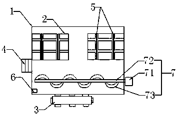
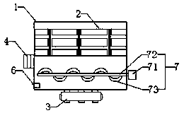
[0020] A high-efficiency ultrasonic cleaning machine, comprising: a cleaning tank 1, a cleaning grid 2, an ultrasonic generator 3, an ultrasonic transducer 4, a heating device 5, a temperature sensor 6 and a controller.

[0021] Wherein, the ultrasonic generator 3 is installed outside the bottom of the cleaning tank 1 , and the ultrasonic transducer 4 is installed on the outer side wall of the cleaning tank 1 and is electrically connected with the ultrasonic generator 3 .

[0022] There are two cleaning racks 2, which are respectively installed on the inner walls of the opposite sides of the cleaning tank 1, that is, one side of each cleaning rack 2 is respectively installed on the inner wall of the corresponding cleaning tank 1. Specifically, the four corners of the side wall of the cleaning grid 2 facing the corresponding side of the cleaning tank are respectively equipped with uprights 21, and the side walls of the cleaning tank are correspondingly equipped with annular slee...

Embodiment 2

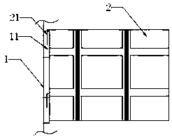
[0026] Please refer to the attached image 3 . The difference from Embodiment 1 is that there is only one cleaning rack 2, and the two ends thereof are respectively installed on the side walls of the cleaning tank 1 on opposite sides. The two ends of the cleaning rack 2 are respectively equipped with columns 21 at one side and four corners of the side wall of the cleaning tank on the corresponding side. The side walls of the cleaning tank are correspondingly equipped with annular sleeves 11, and the columns 21 are inserted and connected to the ring Inside set 11. The fixing between the cleaning grid frame 2 and the cleaning tank 1 is realized. When the size of the cleaning piece is large, install one of the above-mentioned cleaning grids in the cleaning tank, and place the cleaning pieces in the cleaning grid for cleaning. The advantage of installing such a large-size cleaning rack with both ends fixed in the cleaning tank to hold the cleaning parts is that the large-size c...


PUM


Abstract

The invention discloses an efficient ultrasonic cleaning machine. The efficient ultrasonic cleaning machine comprises a cleaning tank, cleaning net racks, an ultrasonic generator, an ultrasonic transducer, heating devices, a temperature sensor and a controller, wherein the ultrasonic generator is installed outside the bottom of the cleaning tank, and the ultrasonic transducer is installed on the outer side wall of the cleaning tank and electrically connected with the ultrasonic generator; the cleaning net racks are installed on the side wall of the top of the cleaning tank, the heating devicesare uniformly arranged on the cleaning net racks, and the temperature sensor is arranged on the side wall of the bottom of the cleaning tank; and the ultrasonic generator, the heating devices and thetemperature sensor are electrically connected with the controller. According to the efficient ultrasonic cleaning machine, the temperature control of a cleaning solution is more stable through the design of the heating devices; the ultrasonic cleaning effect is improved and dead angles are avoided to clean through the design of a stirring device; and the size range of pieces which are applicablefor cleaning is increased through the design of replaceable cleaning net racks, and therefore the practicability of the ultrasonic cleaning machine is improved.

Description

technical field [0001] The invention relates to the field of environmental protection cleaning equipment, in particular to a high-efficiency ultrasonic cleaning machine. Background technique [0002] The ultrasonic cleaning machine uses the cavitation effect, acceleration effect and direct flow effect of ultrasonic waves in the liquid to directly and indirectly affect the liquid and dirt, so that the dirt layer is dispersed, emulsified, and peeled off to achieve the purpose of cleaning. Ultrasonic cleaning technology is one of the commonly used cleaning methods in universities, research institutes, and medical equipment. [0003] The heating device of the existing ultrasonic cleaning machine is usually installed on one side of the cleaning tank to heat the liquid in the entire cleaning tank. Not only is the heating uniformity poor, but once the temperature sensor detects that the temperature of the cleaning liquid exceeds the set value, it will stop heating. Since the heati...

Claims


Application Information

Patent Timeline
Patent Type & Authority Applications(China)
IPC IPC(8): B08B3/12B08B3/10
CPCB08B3/12B08B3/10B08B3/104
Inventor 朱妹珍
Owner 苏州布莱尔仪器有限公司
Why Eureka
Try Eureka