Pipe end forming machine

A forming machine and pipe end technology, applied in the direction of feeding device, positioning device, storage device, etc., can solve the problems of low processing efficiency, long processing time, complicated operation, etc., to improve processing efficiency, reduce processing efficiency, and shorten processing time Effect

Pending Publication Date: 2018-08-24
广州捷晟自动化控制设备有限公司
View PDF1 Cites 7 Cited by
  • Summary
  • Abstract
  • Description
  • Claims
  • Application Information

AI Technical Summary

Problems solved by technology

[0004] The pipe end forming machine of the above-mentioned structure has the following problems: one, the forming machine can only be provided with a forming die, and can only process a pipe end of a shape at a time, for some complex-shaped pipe ends or some processing that requires multiple molding For the pipe end, it is necessary to replace the molding die several times to complete the processing, the operation is complicated, and the processing efficiency is low; 2. The pipe fittings are processed under the action of the molding die. Necking processing at the end, but the forming machine is not equipped with a shrinking processing mechanism, it is necessary to transfer the processed pipe fittings to other machines for processing, which will consume a long processing time, low processing efficiency, and cannot Guaranteed machining accuracy

Method used


Image

  • Pipe end forming machine
  • Pipe end forming machine
  • Pipe end forming machine

Examples


Embodiment 1

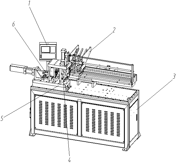
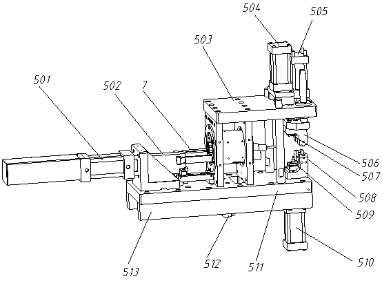
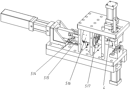
[0028] refer to figure 1 , a pipe end forming machine, including a frame 3 and a control device, the frame 3 is provided with a first forming device 5, the first forming device includes a first bracket, a pushing mechanism, a transposition mechanism and a crimping mechanism, the first The bracket is fixed on the surface of the frame 3, the pushing mechanism is arranged at one end of the first bracket, the clamping mechanism is arranged on the side of the pushing mechanism and fixed on the surface of the first bracket, and the transposition mechanism is located between the pushing mechanism and the clamping mechanism, The transposition mechanism is provided with a punch shaft 6 that runs through the transposition mechanism. One end of the punch shaft 6 is connected to the push mechanism, the other end of the punch shaft 6 is connected to the punch 4, and a feeding device is provided behind the clamping mechanism. The feeding device is fixed on the frame 3, the control device is...

Embodiment 2

[0033] refer to Image 6 , on the basis of Embodiment 1, it also includes a second forming device 8 and a slide rail 9, the second forming device 8 is on the same straight line as the first forming device 5, the second forming device 8 includes a second bracket, a clamping Mechanism, processing mechanism and moving mechanism, the second support includes the second upper fixed plate 802 and the second lower fixed plate 810 parallel to each other, the second upper fixed plate 802 and the second lower fixed plate 810 are connected by the pressing table column, the second The lower surface of the lower fixed plate 810 is connected with a slide block 4, the slide block 4 is slidably connected on the slide rail 9, the slide rail 9 is fixed on the surface of the frame 3, the clamping mechanism is arranged on one end of the second lower fixed plate 810, and the processing mechanism Set on the other end of the second lower fixing plate 810 , the moving mechanism is located below the se...


PUM


Abstract

The invention discloses a pipe end forming machine comprising a rack and a control device. The rack is provided with a first forming device. The first forming device comprises a first bracket, a pushmechanism, a transposition mechanism and a clamping and pressing mechanism. The first bracket is fixed to the rack, the push mechanism is arranged at one end of the first bracket, and the clamping andpressing mechanism is arranged on the side face of the push mechanism and is connected with the first bracket. The transposition mechanism is arranged between the push mechanism and the clamping andpressing mechanism, and the transposition mechanism is internally provided with a punch shaft. One end of the punch shaft is connected with the push mechanism, the other end of the punch shaft is connected with a punch, and a feeding device is arranged behind the clamping and pressing mechanism and is fixed to the rack. The control device is connected with the push mechanism, the transposition mechanism and the clamping and pressing mechanism, and the control device is arranged on the rack. The pipe end forming machine is high in automated degree and high in machining efficiency, dies can be replaced automatically, and pipe ends of various shapes can be machined.

Description

technical field [0001] The invention relates to the technical field of pipe making, in particular to a pipe end forming machine. Background technique [0002] With the development of society and the advancement of science and technology, pipe fittings engineering is developing towards high strength and high toughness, the quality requirements for pipe fittings are constantly improving, and pipe making technology and equipment are also constantly developing. Among them, the pipe end forming machine is a machine widely used in pipe making to form the end of pipe fittings. It is suitable for pipe insertion, automobile oil pipes, air pipes, water pipes, and air-conditioning pipes of various shapes. Molding processing. [0003] Chinese patent publication CN105964750A discloses a pipe end forming machine, including a frame, on which a clamping mechanism is provided, and one side of the clamping mechanism is provided with a forming mechanism, and the clamping mechanism includes a ...

Claims


Application Information

Patent Timeline
Patent Type & Authority Applications(China)
IPC IPC(8): B21D19/08B21D41/04B21D43/00
CPCB21D19/08B21D41/04B21D43/003B21D43/006
Inventor 祝金波
Owner 广州捷晟自动化控制设备有限公司
Why Eureka
Try Eureka