
Oil supporting positioning device for machining of thin-walled spherical workpiece

A support positioning and spherical technology, which is applied in the direction of positioning devices, grinding workpiece supports, metal processing equipment, etc., can solve the problems of unfavorable inner and outer spherical surface finishing, lower processing quality, workpiece deformation, etc., so as to avoid workpiece deformation and improve quality , the effect of absorbing vibration

Pending Publication Date: 2018-08-24
WUJIANG TIANLONG MACHINERY
View PDF11 Cites 10 Cited by
  • Summary
  • Abstract
  • Description
  • Claims
  • Application Information

AI Technical Summary

Problems solved by technology

[0003] 1) Due to the rigid contact between the thin-walled workpiece and the tooling fixture, and the characteristics of the thin-walled workpiece itself, the thin-walled workpiece and the tooling fixture resonate during the processing process, which is not conducive to the finishing of the inner and outer spherical surfaces, and will lead to a reduction in processing quality
[0004] 2) If the pressure generated by the air compressor or hydraulic machine is not properly controlled, it is easy to cause deformation of the workpiece, and even if the pressure is properly controlled during processing, because the workpiece is supported by external force, once the external support is released, it is still very easy to cause deformation of the workpiece, and in severe cases, the product will be scrapped

Method used


Image

  • Oil supporting positioning device for machining of thin-walled spherical workpiece
  • Oil supporting positioning device for machining of thin-walled spherical workpiece
  • Oil supporting positioning device for machining of thin-walled spherical workpiece

Examples


Embodiment

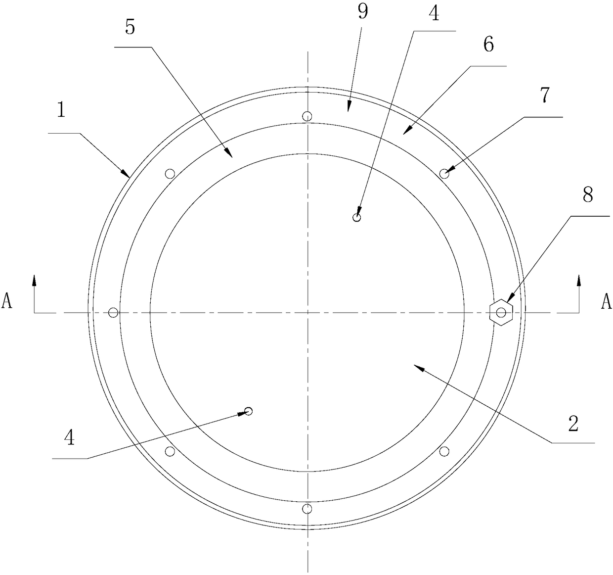
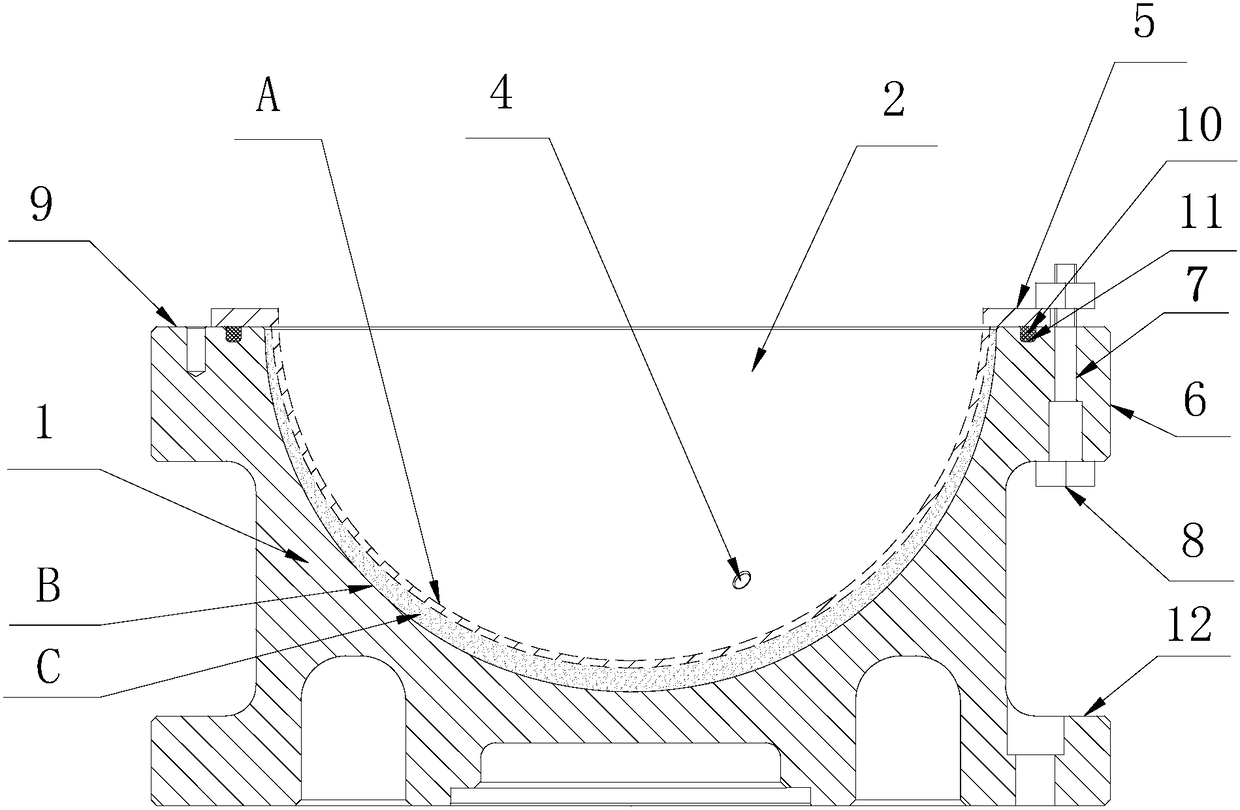
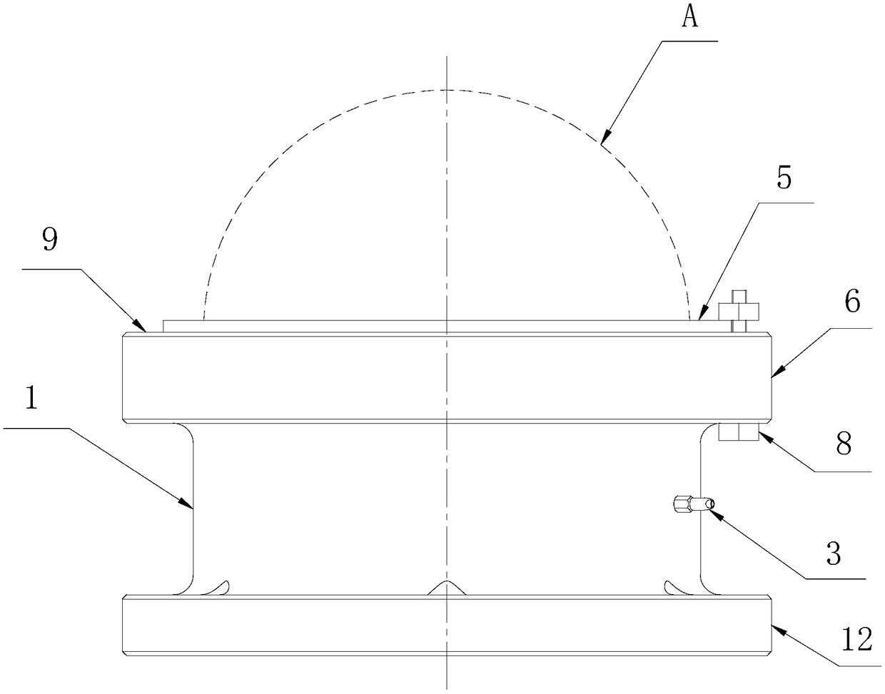
[0024] Example: Combining Figure 1~Figure 3 The specific implementation of the grease supporting and positioning device for processing thin-walled spherical workpieces provided by the present invention is described as follows: it has a support base 1, an annular pressure plate 5 and a sealing ring 10, and the top of the support base 1 has a table 9. The table 9 is provided with a hemispherical groove 2 for the thin-walled spherical workpiece A to be embedded, and the outer wall of the support base 1 is provided with an oil injection nozzle 3, and the inner wall of the hemispherical groove 2 is provided with an oil injection hole 4 communicating with the oil injection nozzle 3. In this embodiment, the number of the oil injection holes 4 is two, and they are all connected to the oil injection nozzle 3 via an oil pipeline provided inside the support base 1. And the two oil injection holes 4 are distributed symmetrically about the center of the hemispherical groove 2, such as figu...


PUM


Abstract

The invention discloses an oil supporting positioning device for machining of a thin-walled spherical workpiece. The oil supporting positioning device comprises a supporting pedestal. The top of the supporting pedestal is provided with a table board. The oil supporting positioning device is characterized in that the table board is provided with a semispherical groove allowing the thin-walled spherical workpiece to be embedded in; an oil filling nozzle is arranged on the outer wall of the supporting pedestal; oil filling holes communicating with the oil filling nozzle are formed in the inner wall of the semispherical groove; the oil supporting positioning device further comprises an annular pressing plate used for fixing the thin-walled spherical workpiece; a circle of positioning flange isarranged on the periphery of the upper portion of the supporting pedestal integrally; the positioning flange is provided with a plurality of positioning holes used for arranging bolts in a penetrating mode so that the annular pressing plate can be locked to the table board; the inner edge of the annular pressing plate inwards extends our of the inner wall of the semispherical groove; and after the thin-walled spherical workpiece is arranged in the semispherical groove, an oil filling cavity for oil filling is formed among the annular pressing plate, the outer wall of the thin-walled sphericalworkpiece and the inner wall of the semispherical groove. Through the device, the thin-walled spherical workpiece can be better supported, resonance is avoided, in addition, pressure does not need tobe applied through an air compressor or an oil press, and the workpiece is prevented from being deformed.

Description

Technical field [0001] The invention relates to a grease support positioning device for processing thin-walled spherical workpieces. Background technique [0002] At present, when processing thin-walled spherical workpieces on lathes and grinders, air compressors or hydraulic machines are mainly used to pressurize and fix the workpieces, and then the outer or inner spherical surfaces of the workpieces are polished, but the disadvantages are as follows: [0003] 1) Due to the rigid contact between the thin-walled workpiece and the fixture and the characteristics of the thin-walled workpiece itself, the thin-walled workpiece and the fixture will resonate during the machining process, which is not conducive to the finishing of the inner and outer spherical surfaces, which will result in a decrease in processing quality. [0004] 2) If the pressure generated by the air compressor or hydraulic press is not properly controlled, it is easy to cause deformation of the workpiece, and even if ...

Claims


Application Information

Patent Timeline
Patent Type & Authority Applications(China)
IPC IPC(8): B23Q3/06B23Q11/10F16N1/00B24B41/06
CPCF16N1/00B23Q3/065B23Q11/10B24B41/067
Inventor 施国春过伟
Owner WUJIANG TIANLONG MACHINERY
Learn More