
Method for precisely grinding small roller of bearing with automatic grinding device

A high-precision, grinding technology, which is applied in the direction of grinding drive devices, grinding machine parts, and machine tools designed for grinding the rotating surface of workpieces, etc., can solve the contact instability of the pallet working surface, grinding wheel and guide wheel And other parts wear, affect the machining accuracy and consistency and other issues, to achieve the effect of stable and reliable quality, low grinding cost, and improve grinding accuracy and efficiency

Active Publication Date: 2018-08-24
LUOYANG LIBO NUMERICAL CONTROL TECH CO LTD
View PDF6 Cites 2 Cited by
  • Summary
  • Abstract
  • Description
  • Claims
  • Application Information

AI Technical Summary

Problems solved by technology

Although centerless cylindrical grinding has high production efficiency and is easy to realize automation and mass production, its machining accuracy depends heavily on the mechanical structure and precision of the grinding machine, and there are still changes in the position of the workpiece center, linear motion of the workpiece center and the axis of the grinding wheel. Errors, errors between the workpiece and the movement speed, the instability of the contact of the pallet working surface, and the wear of the grinding wheel and guide wheel itself have greatly affected the improvement of machining accuracy and consistency.
Therefore, the existing centerless cylindrical grinding technology and grinding machines are difficult to meet the needs of the market, and further in-depth research and upgrading are required on the processing principle, grinding machine structure and processing technology.

Method used


Image

  • Method for precisely grinding small roller of bearing with automatic grinding device
  • Method for precisely grinding small roller of bearing with automatic grinding device
  • Method for precisely grinding small roller of bearing with automatic grinding device

Examples


Embodiment Construction

[0022] The present invention is a method for high-precision grinding of small bearing rollers by an automatic grinding device. The outer diameter of the small bearing rollers is less than 10mm. The automatic grinding device of the present invention realizes the centerless grinding of the small bearing rollers. grinding, and the grinding accuracy of the small roller of the bearing is greatly improved.

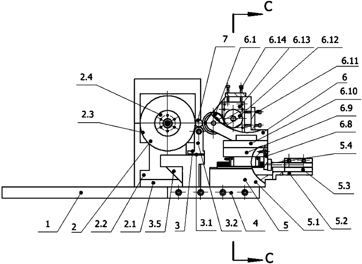
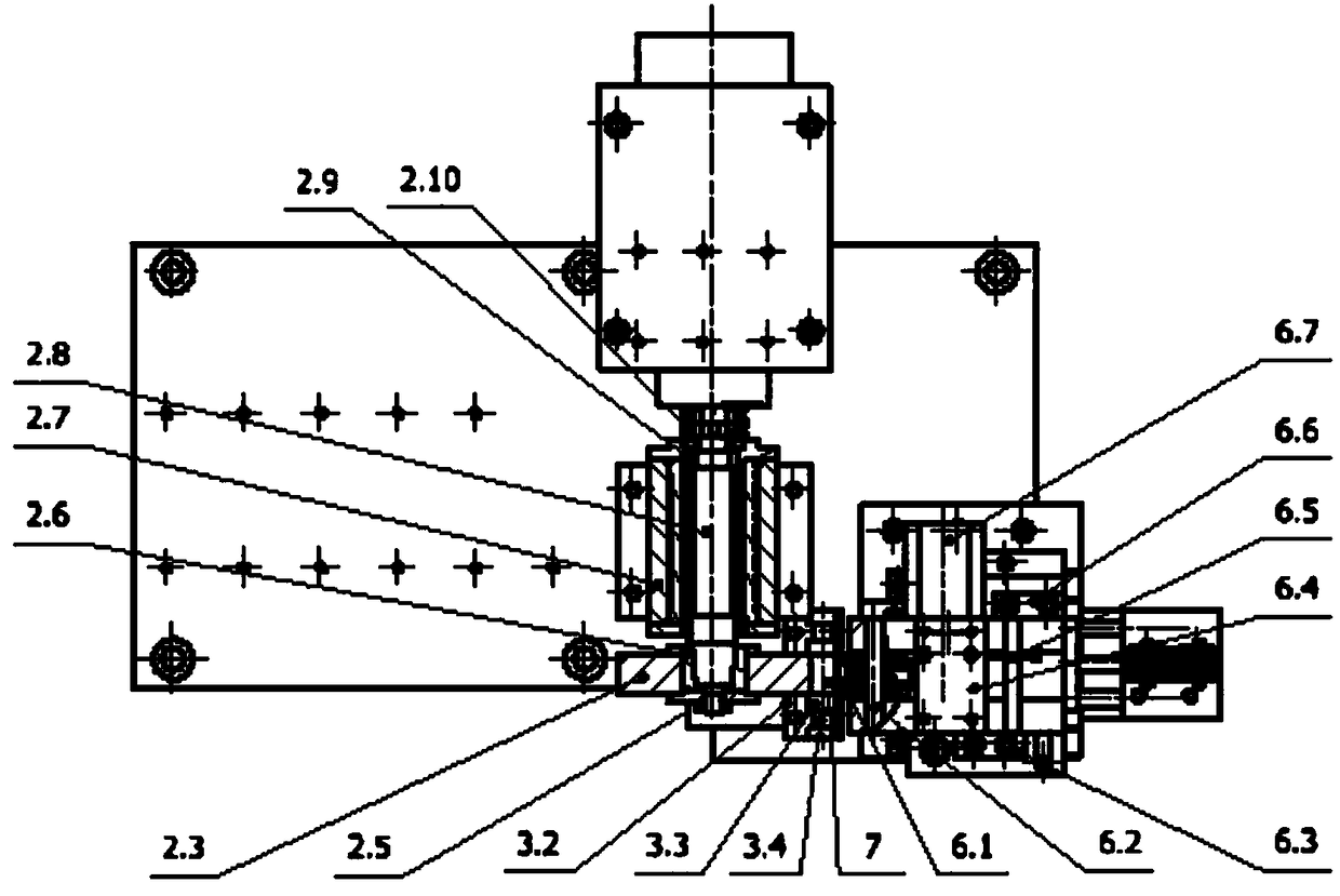
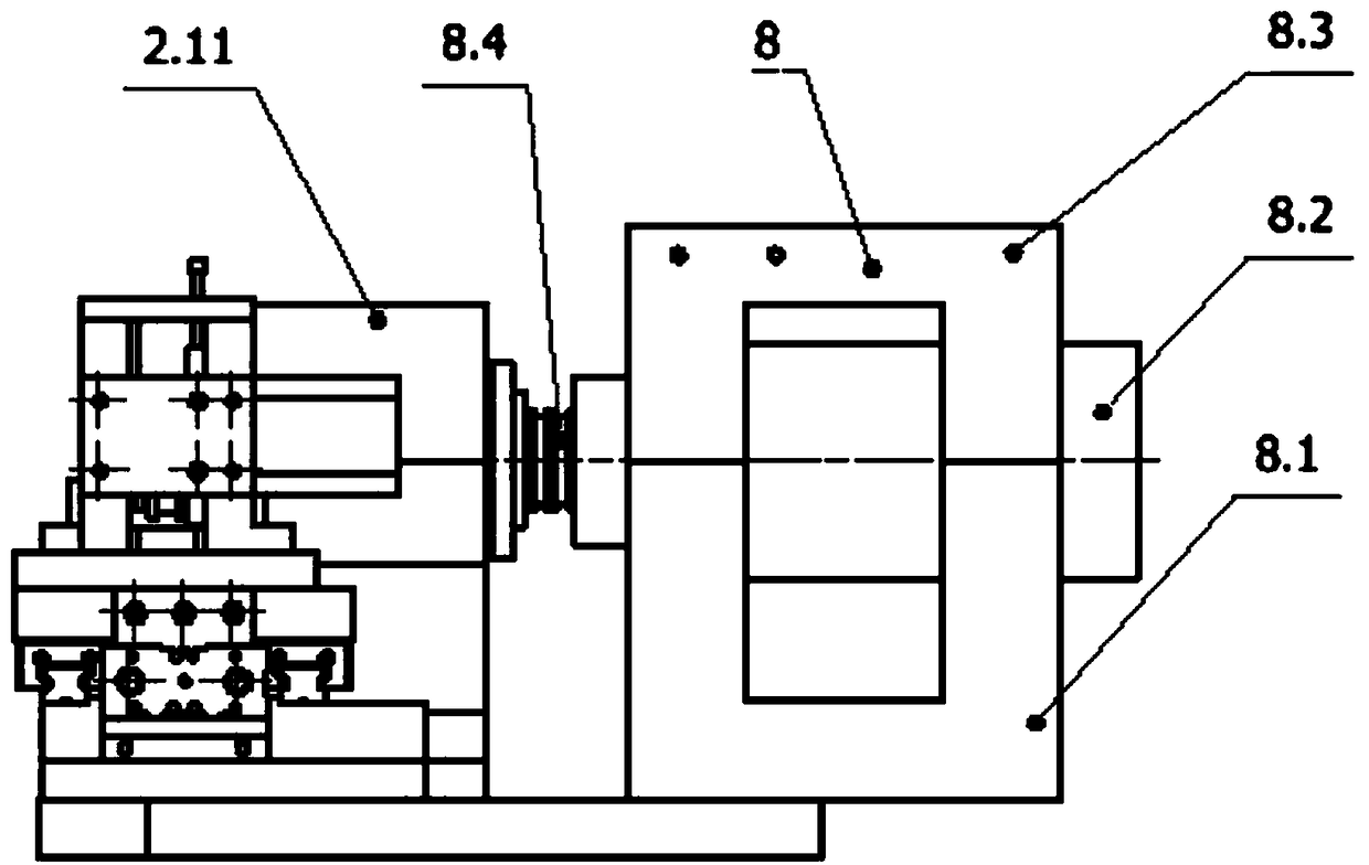
[0023] combine Figure 1-4 , the automatic grinding device of the present invention includes a base plate 1, a grinding wheel device 2, a support wheel device 3, an additional plate 4 for the base plate, a guide wheel lateral feed device 5, a guide wheel driving device 6 and an electric spindle device 8, wherein the grinding wheel device 2 Contains insulating plate 2.1, grinding wheel spindle support 2.2, grinding wheel 2.3, grinding wheel gland 2.4, nut 2.5, grinding wheel taper sleeve 2.6, bearing seat 2.7, grinding wheel spindle 2.8, lock nut 2.9, grinding wheel spindle conne...


PUM


Abstract

The invention relates a method for precisely grinding a small roller of a bearing with an automatic grinding device. The automatic grinding device comprises a baseplate, a grinding wheel device, a supporting wheel device, a baseplate additional plate, a guide wheel transverse feed device, a guide wheel driving device and an electric spindle device; a small roller is placed on a supporting wheel between a grinding wheel and a guide wheel in the perpendicular direction during grinding, and the small roller does not need to be centered and supported by an ejector pin; the excircle of the ground small roller is regarded as the location datum, and the grinding wheel and the guide wheel are rotated in the same direction; the circumferential velocity of the guide wheel is very low, and is 20-30 m / min, and the circumferential velocity of the grinding wheel is 60-80 times the circumferential velocity of the guide wheel; the small roller is rotated under the effect of friction force between thegrinding wheel and the small roller as well as between the guide wheel and the small roller, and large linear velocity difference exists at the contact area between the small roller and the grinding wheel so that materials are removed; in order to ensure the excircle roundness of the small roller, the center height of the small roller is the same as the center height of the grinding wheel; and thecenter of the guide wheel is higher 2-3 nm than a line connecting the axis of the small roller with the axis of the grinding wheel.

Description

technical field [0001] The invention belongs to the technical field of bearing roller grinding, and in particular relates to a method for high-precision grinding of small bearing rollers by an automatic grinding device. Background technique [0002] The grinding of the crown of the small roller of the bearing generally adopts the centerless cylindrical grinding technology. The method of the centerless cylindrical grinding technology to form the crown curve is the fan Cheng method. Face profile shape. Although centerless cylindrical grinding has high production efficiency and is easy to realize automation and mass production, its machining accuracy depends heavily on the mechanical structure and precision of the grinding machine, and there are still changes in the position of the workpiece center, linear motion of the workpiece center and the axis of the grinding wheel. Errors, errors between the workpiece and the speed of movement, the instability of the contact of the pall...

Claims


Application Information

Patent Timeline
Patent Type & Authority Applications(China)
IPC IPC(8): B24B5/26B24B47/12B24B41/04B24B5/307B24B5/30B24B41/02B24B47/20B24B47/00
CPCB24B5/26B24B5/30B24B5/307B24B41/02B24B41/04B24B47/00B24B47/12B24B47/20
Inventor 张洛平李华张晓蕙
Owner LUOYANG LIBO NUMERICAL CONTROL TECH CO LTD
Learn More