Hanging connecting structure of power battery box body and universal mounting method thereof

A technology of power battery and connection structure, applied in the direction of power unit, electric power unit, transportation and packaging, etc., can solve the problems of inability to install directly, unstable installation, difficult adjustment of installation error, etc., to increase connection and local strength, installation The effect of high strength and strong installation versatility

Active Publication Date: 2018-08-24
DONGFENG MOTOR CORP HUBEI
View PDF7 Cites 3 Cited by
  • Summary
  • Abstract
  • Description
  • Claims
  • Application Information

AI Technical Summary

Problems solved by technology

[0004] When installing the rear end of the power battery box, it is most convenient to install it directly on the middle beam of the rear floor; in order to ensure sufficient clearance between the rear end of the power battery box and the rear axle, the rear end of the power battery box cannot be directly installed on the rear axle. It is on the middle beam of the floor, and hangs under the front and lower side of the middle beam of the rear floor; if a strengthening connector is directly added to fix the rear end of the battery box, it is inconvenient to install, and it is not easy to adjust when there is a certain installation error
[0005] When the same type of power battery box is arranged on models with different wheelbases, especially on models with short wheelbases, there will also be installation point offsets, which cannot be installed on the side rails or inner rails of the car, making When the left and right ends of the power battery box are installed, the installation strength is insufficient, the installation is unstable, and the installation versatility requirements of different models cannot be met

Method used


Image

  • Hanging connecting structure of power battery box body and universal mounting method thereof
  • Hanging connecting structure of power battery box body and universal mounting method thereof
  • Hanging connecting structure of power battery box body and universal mounting method thereof

Examples


Embodiment Construction

[0044] The present invention will be described in further detail below in conjunction with the accompanying drawings to facilitate a clearer understanding of the present invention, but the present invention is not limited to the following specific embodiments.

[0045] "Front" and "rear" in the present invention refer to the X direction of the vehicle, that is, the longitudinal direction of the vehicle. The "first", "second", "third", "fourth" and "fifth" mentioned in the present invention are only to distinguish and describe each component, and there is no distinction of importance or order.

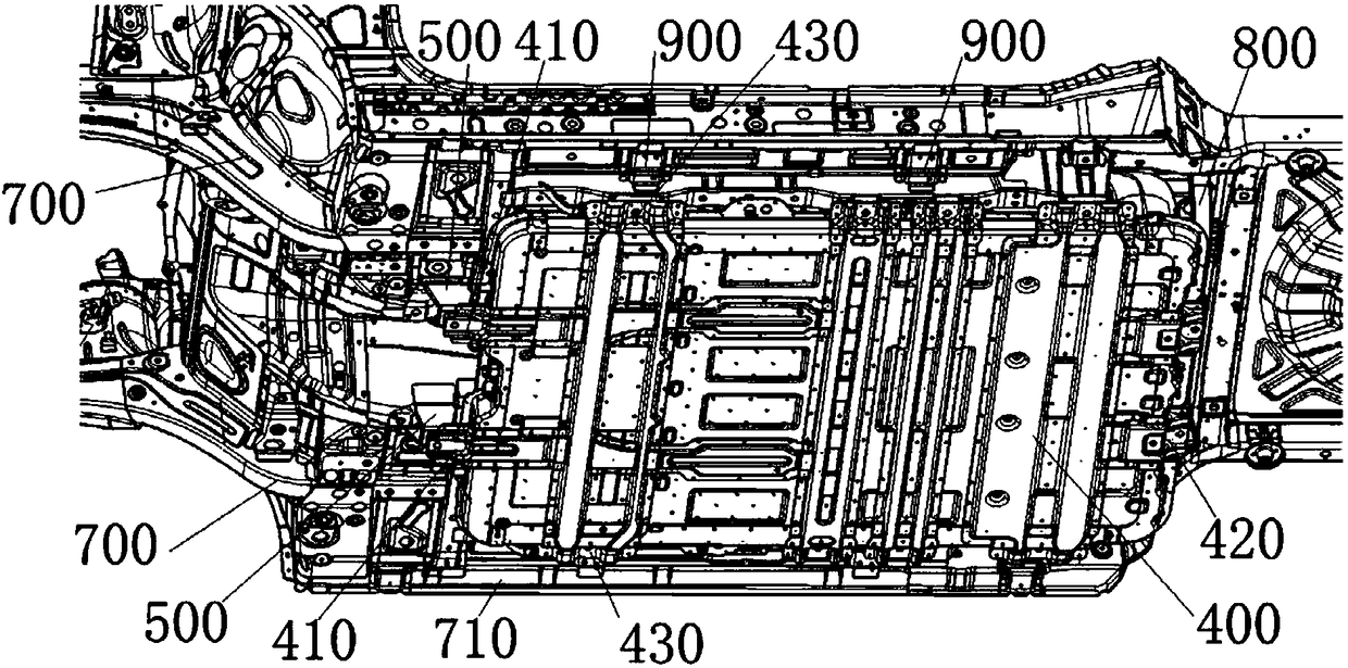
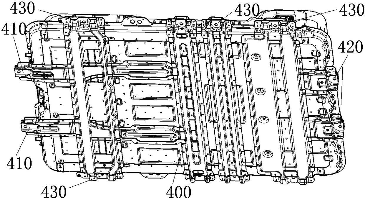
[0046] like figure 2 and Figure 8 As shown, the power battery box 400 of the present invention is an integrated body of a modular power battery and an external box, and the power battery box 400 of the present invention is based on the same modular model of the power battery box The installation of the 400 on the car floor enables the power battery box 400 to be installed on pure el...


PUM


Abstract

The invention discloses a hanging connecting structure of a power battery box body. The hanging connecting structure comprises the power battery box body and floor skeleton beams around the power battery box body. Hanging points of the supporting portions of the front end or/and the rear end or/and the side end of the power battery box body are located in non-beam areas outside the floor skeletonbeams, and the non-beam areas are provided with reinforcing brackets which can be connected with the floor skeleton beams and the front end or/and the rear end or/and the side end of the power batterybox body. The reinforcing brackets include a hanging bracket installed in the first non-beam area, a U-shaped bracket installed in the second non-beam area and telescopic connecting plates installedin the third non-beam area. The invention further discloses a universal installation method of the power battery box body. The hanging connecting structure of the power battery box body and the universal mounting method thereof provide front, rear and side portion mounting points with sufficient strength for battery electric vehicles with different wheelbases and different wheel tracks without changing the overall structure of a vehicle body, and increase the installation universality of the same modular power battery box body.

Description

technical field [0001] The invention belongs to the technical field of new energy automobile parts, in particular to a hanging connection structure of a power battery box and a general installation method thereof. Background technique [0002] As a new energy vehicle, a pure electric vehicle is mainly driven by electric energy. Therefore, it is necessary to design the box body of the battery and the connection structure between the box body and other components on the vehicle body. In order to adapt to a variety of models and speed up the pace of production, when designing auto parts, some parts that can be shared are usually made into modules and integrated to increase the performance of the vehicle. [0003] The cost of power batteries for new energy vehicles is extremely high. Modular development of power batteries and their installation boxes can reduce costs and shorten the production cycle. However, different models have different lengths, widths, heights, wheelbases...

Claims


Application Information

Patent Timeline
Patent Type & Authority Applications(China)
IPC IPC(8): B60K1/04
CPCB60K1/04B60K2001/0438
Inventor 李仲奎樊树军周全陈孟华袁亮吴开丰李华香顿栋梁王辉
Owner DONGFENG MOTOR CORP HUBEI
Why Eureka
Try Eureka