
Clamping mechanism of quenching machine

A technology of clamping mechanism and quenching machine, which is applied in the field of quenching machine, can solve the problems of corrosion and rust of the driving mechanism, and achieve the effect of improving the quality of quenching and the process of quenching is stable and efficient

Pending Publication Date: 2018-08-24
台州市索立机械有限公司
View PDF6 Cites 0 Cited by
  • Summary
  • Abstract
  • Description
  • Claims
  • Application Information

AI Technical Summary

Problems solved by technology

[0003] At present, the driving mechanism and the workpiece of the existing quenching machine are set in the same water tank, and the entire driving mechanism is soaked in coolant or water for a long time during the quenching process, which may easily cause corrosion and rust of the driving mechanism. Now our company produces To produce a quenching machine that can effectively extend the working life, how to provide an adaptive clamping mechanism has become a technical problem that needs to be solved urgently

Method used


Image

  • Clamping mechanism of quenching machine
  • Clamping mechanism of quenching machine

Examples


Embodiment Construction

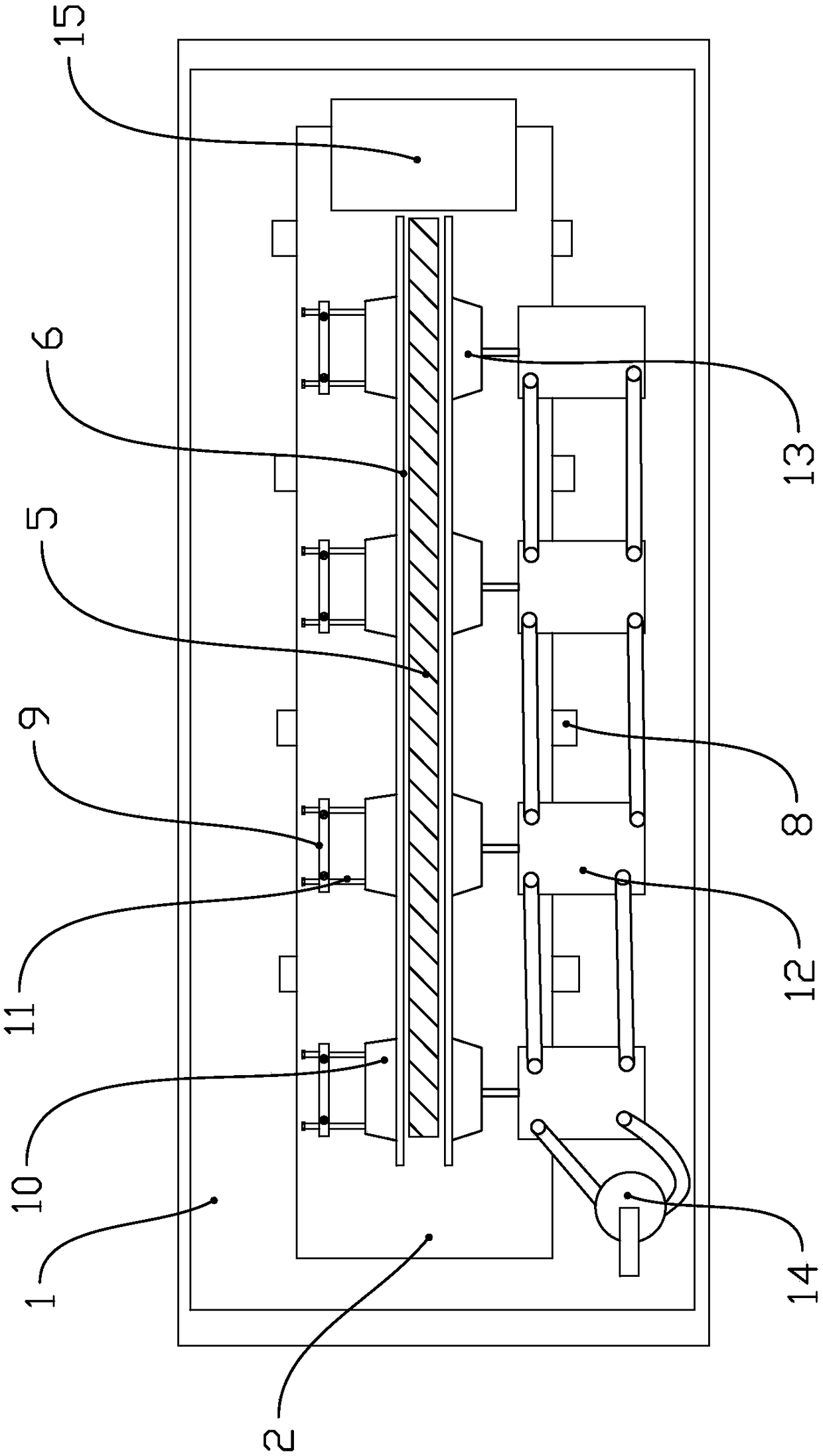
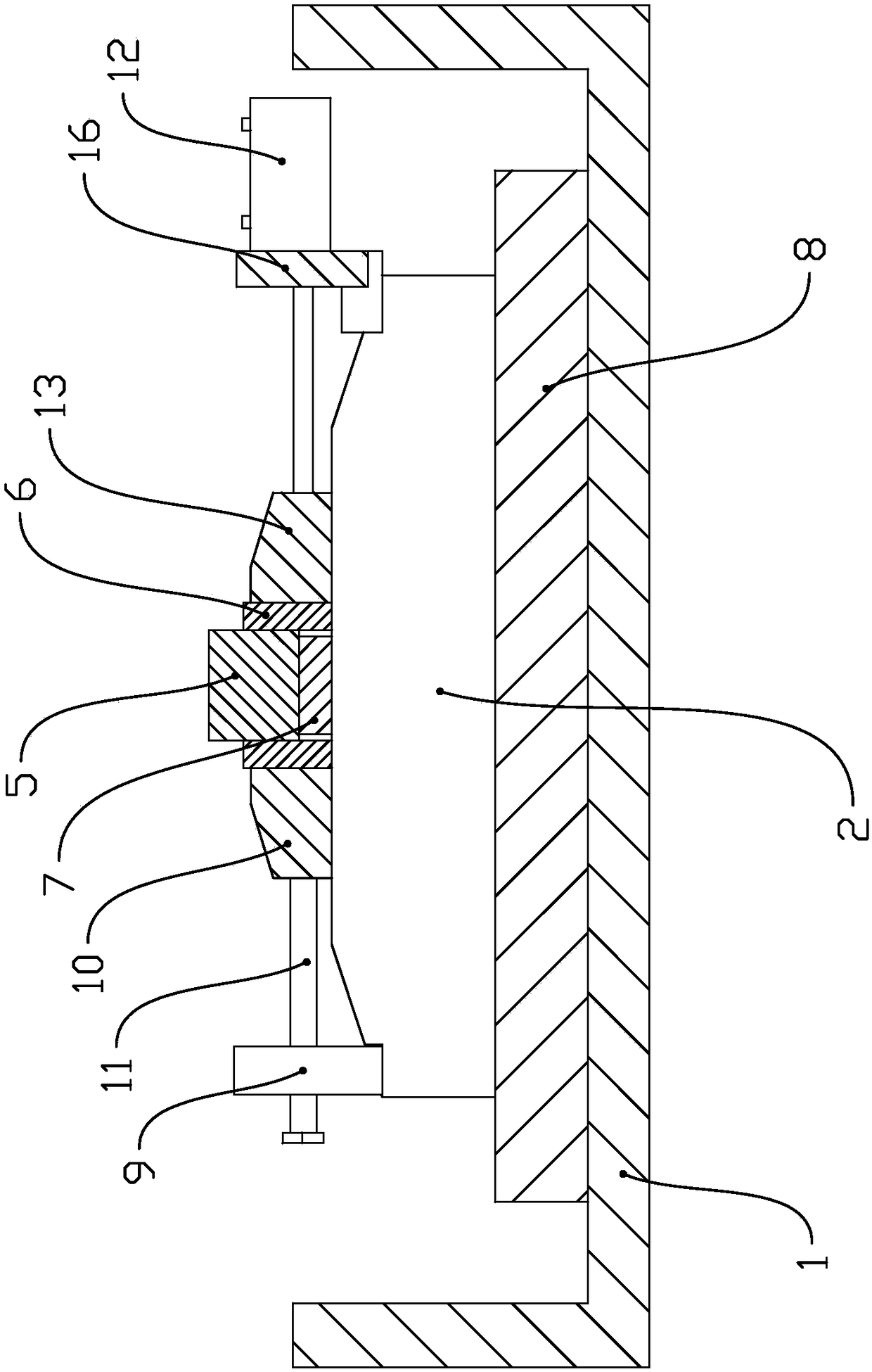
[0022] Below in conjunction with accompanying drawing, the present invention will be further described with specific embodiment, see figure 1 -2:

[0023] The clamping mechanism of this quenching machine includes a workbench 2 arranged in the water tank 1. The rear end of the workbench 2 is provided with supports at intervals along the transverse direction, and the front end of the workbench 2 is provided with supports corresponding to the supports at intervals along the transverse direction. Drive the workpiece 5 against the driver fixed on the front side of the support; the bottom of the water tank 1 is fixed with support rods 8 at intervals along the transverse direction, and the workbench 2 is fixed on the support rods 8; further, the upper end of the workbench 2 is trapezoidal, The upper surface of the workbench 2 is a horizontal plane, and the left and right sides of the workbench 2 upper end are provided with inclined surfaces that are high inside and low outside, and a...


PUM


Abstract

The invention provides a clamping mechanism of a quenching machine, belongs to the technical field of quenching machines, and solves the technical problems that an existing clamping mechanism is instable to clamp a workpiece and incapable of draining. The clamping mechanism of the quenching machine comprises a workbench arranged in a water tank, wherein support pieces are arranged at the rear endpart of the workbench along a horizontal direction in a spaced manner; and drive pieces corresponding to the support pieces and capable of driving the workpieces to be abutted against and fixed to thefront sides of the support pieces are arranged at the front end part of the workbench along the horizontal direction in the spaced manner. According to the clamping mechanism of the quenching machineprovided by the invention, when the workbench is arranged, the fixing position of the workpiece is lower than the bottom part of the water tank, so that the occurrence of the phenomenon that the workpiece continuously contacts quenched hot water so as to affect a quenching effect is avoided, and the quenching quality is favorably improved; and through cooperatively arranging the support pieces and the drive pieces, the workpiece can be better fixed, and a quenching process is more sable and high-efficient.

Description

technical field [0001] The invention belongs to the technical field of quenching machines, in particular to a clamping mechanism of a quenching machine. Background technique [0002] Quenching refers to a heat treatment method that uses high-frequency current (30K-1000KHZ) to locally heat and cool the surface of the workpiece to obtain a surface hardened layer. The quenching machine adopts induction heating, and the engineer explained the principle of induction heating as follows: the workpiece is placed in the inductor, and the inductor is generally a hollow copper tube that inputs intermediate frequency or high frequency alternating current (1000-300000Hz or higher). An alternating magnetic field is generated to generate an induced current of the same frequency in the workpiece. The distribution of this induced current in the workpiece is uneven, strong on the surface, but weak in the interior, and close to 0 in the center. Using this eddy current and collection The skin ...

Claims


Application Information

Patent Timeline
Patent Type & Authority Applications(China)
IPC IPC(8): C21D1/63
CPCC21D1/63
Inventor 吴世强罗永敏
Owner 台州市索立机械有限公司
Learn More