

Imaging flash stick
A flash stick and imaging technology, applied in the field of imaging flash sticks, can solve the problems of instability, incomplete display, uneven speed of the waving process, etc., and achieve the effects of simple structure, large display area and stable display effect.
- Summary
- Abstract
- Description
- Claims
- Application Information
AI Technical Summary
Problems solved by technology
Method used
Image

Examples
specific Embodiment approach 1
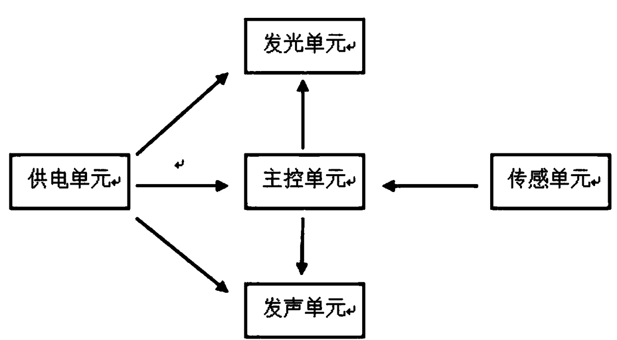
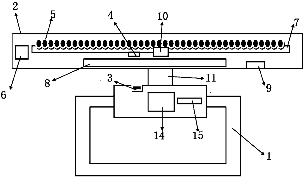
[0040] In this embodiment, the handle 1 is located directly below the middle of the flashing main body 1. The shape of the handle 1 is "mouth", which is suitable for children's toys. The flashing main body 1 is a hollow shell, and a circuit board 7 is arranged inside it. The surface is provided with an LED light 5 display unit, the back of the circuit board is provided with a Hall sensor 4, the handle 1 is provided with a magnetic block 3, the rotating connector is a buckle 11, and the buckle 11 is integrally connected with a Ratchet mechanism, the ratchet mechanism includes 14 ratchets and 15 ratchets, the buckle 11 is fixedly connected to the handle 1, the buckle 11 can be fastened to the light emitting body 2, and the handle 2 can be separated from the flashing body 1 as required.
[0041] The imaging flash stick provided in this embodiment is a common version without USB and storage unit, the flash main body 1 is provided with a switch 9, the power supply unit is a battery ...
specific Embodiment approach 2
[0044] The difference between this specific embodiment and specific embodiment 1 is that the imaging flash stick provided in this example is a high-end version with a USB and a storage unit. The handle 1 of this embodiment is located directly below the middle of the flash main body 1, and the shape of the handle 1 is a ring The flashlight body 2 is provided with a USB interface 10, and the storage unit stores information transmitted through the USB interface 10. The main control unit is controlled by a single-chip microcomputer, and the single-chip microcomputer model is STM32F103C8T6. This type of single-chip microcomputer can display color and monochrome. The main control unit will be recognized as a U disk by the computer when it is connected to the computer through USB. When changing the content, only need to put the processed image file into the U disk, and then the main control unit The control unit sends it to the storage unit to replace or delete existing data.
[004...
specific Embodiment approach 3
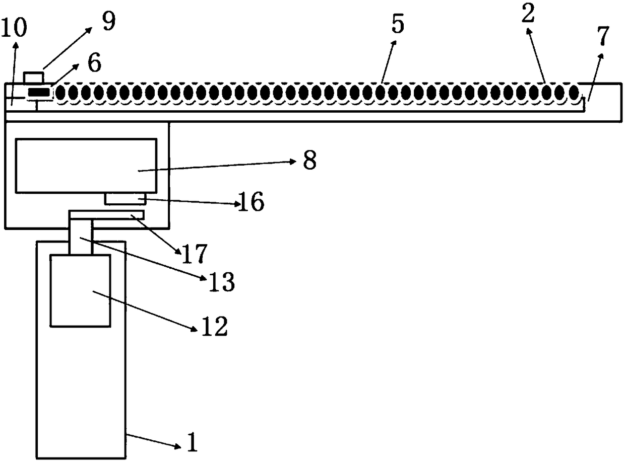
[0046] The rotating connector of the imaging flash stick provided in this embodiment is the rotating shaft 13, which is set in the rotating shaft sleeve 12, and the blocking plate 17 is also arranged above the rotating shaft 13, and the rotating shaft sleeve is located in the handle 1, and the handle 1 and flashing main body 2 are designed in an "L" shape, which is suitable for concerts and celebrations. The flash body 2 of the imaging flash stick provided in this specific embodiment is provided with a storage unit, the flash body 1 is provided with a switch 9, the power supply unit is a battery 8, and the main control unit and the storage unit are all arranged on the circuit board 7 Above, the flash main body 2 is also provided with a USB interface 10 , and the shown sensing unit is an infrared sensor 16 . Such as image 3 shown. Every time the flashing main body 2 rotates one revolution, the infrared sensor 16 will sweep the shutter 17 once, and then the signal is transmit...
PUM
 Abstract
Description
Claims
Application Information