Method, device and system for detecting road surface conditions through depth camera

A road state and depth camera technology, applied in measurement devices, control/adjustment systems, two-dimensional position/channel control, etc., can solve the problems of detection failure and incomplete detection points, and achieve low detection costs and avoid damage. Effect

Inactive Publication Date: 2018-08-24
ZHEJIANG JIESHANG ARTIFICIAL INTELLIGENCE RES & DEV CO LTD
View PDF5 Cites 6 Cited by
  • Summary
  • Abstract
  • Description
  • Claims
  • Application Information

AI Technical Summary

Problems solved by technology

[0004] In order to overcome the deficiencies of the prior art, the object of the present invention is to provide a method, device and system for detecting the state of the road surface using a depth camera, aiming at solving the problem that the prior art uses point laser ranging to realize robot obstacle avoidance due to incomplete detection points. Probing the problem of failure

Method used


Image

  • Method, device and system for detecting road surface conditions through depth camera
  • Method, device and system for detecting road surface conditions through depth camera
  • Method, device and system for detecting road surface conditions through depth camera

Examples


specific Embodiment 1

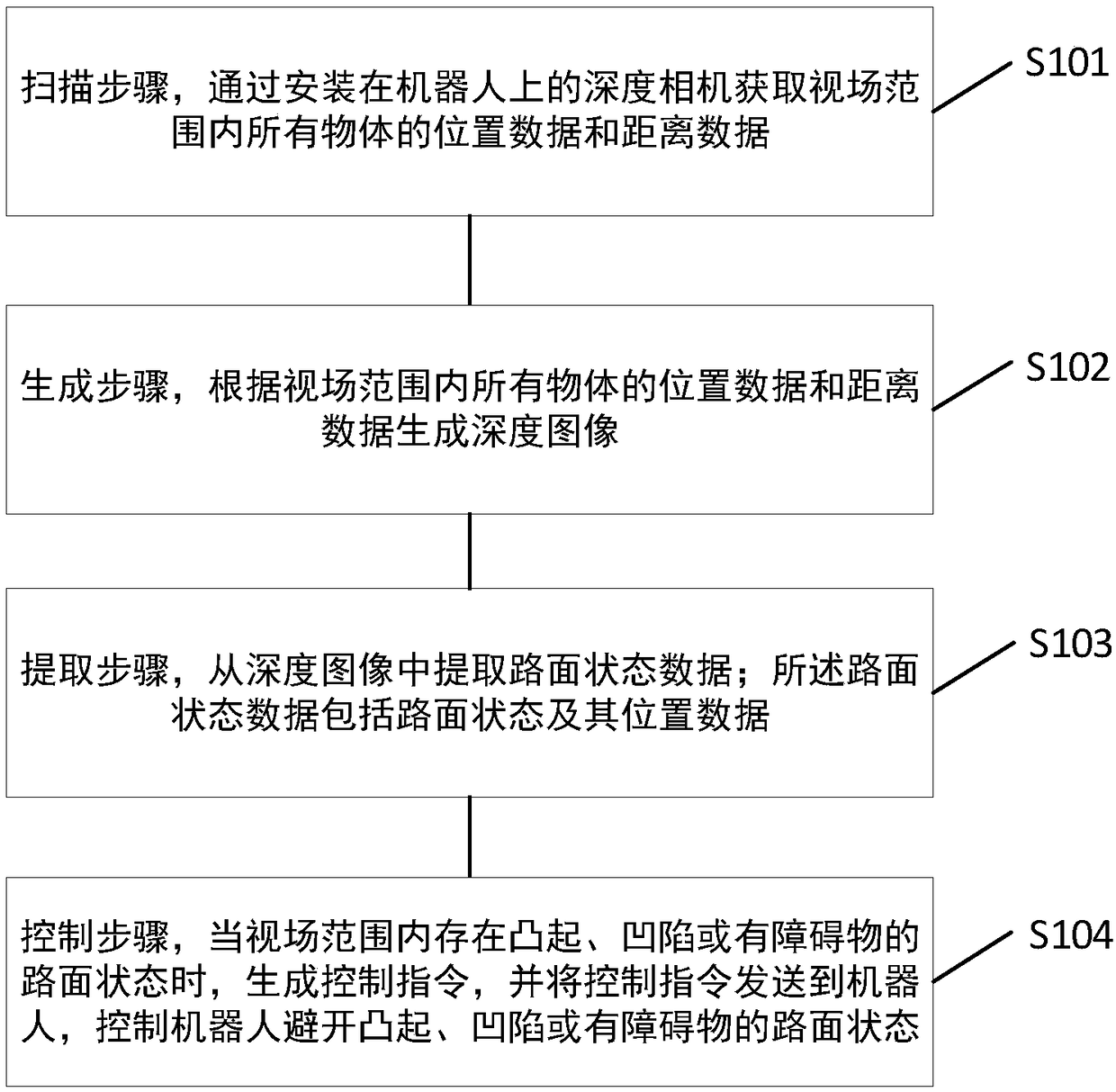
[0034] Such as figure 1 As shown, the embodiment of the present invention provides a method for detecting road surface state using a depth camera, including:

[0035] Scanning step S101, obtaining the position data and distance data of all objects within the field of view through the depth camera installed on the robot;

[0036] Generating step S102, generating a depth image according to the position data and distance data of all objects within the field of view;

[0037] Extracting step S103, extracting road surface state data from the depth image; the road surface state data includes road surface state and its position data.

[0038] The embodiments of the present invention do not limit the types and names of road surface states. Preferably, the road surface states may include flat, convex, concave, and obstacles. In the process of classifying the state of the road surface, preferably, the state of the road surface may also include approximately smooth. That is, the bumps...

specific Embodiment 2

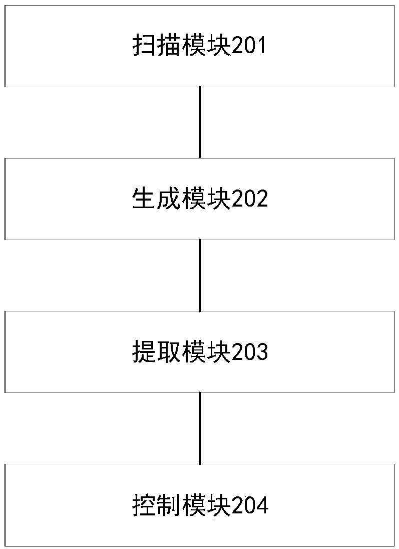
[0042] Such as figure 2 As shown, an embodiment of the present invention provides a device for detecting road surface conditions using a depth camera, including:

[0043] The scanning module 201 is used to obtain the position data and distance data of all objects within the field of view through the depth camera installed on the robot;

[0044] A generation module 202, configured to generate a depth image according to the position data and distance data of all objects within the field of view;

[0045] The extraction module 203 is configured to extract road surface state data from the depth image; the road surface state data includes road surface state and its position data.

[0046] Preferably, the road surface state may include smooth, convex, concave, and road surface states with obstacles.

[0047] Preferably, the embodiment of the present invention may also include a control module 204, configured to: generate a control instruction when there is a road surface state wi...

specific Embodiment 3

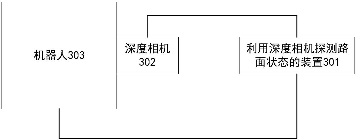
[0049] Such as image 3 As shown, an embodiment of the present invention provides a system for detecting road surface conditions using a depth camera, including:

[0050] The device 301 for detecting the state of the road surface using a depth camera in the second embodiment;

[0051] The depth camera 302 is installed on the robot 303, and the depth camera 302 is used to obtain position data and distance data of all objects within the field of view;

[0052]The robot 303 is used to avoid bumps, depressions or road conditions with obstacles according to control instructions.

[0053] Preferably, the robot 303 can also be used to send an alarm message to the device 301 when there is a problem in traveling. The advantage of this is that when there is a problem with the scanning process of the depth camera 302, or when there is a problem with the algorithm of the device 301 that causes the robot 303 to run into a problem, the robot 303 can also report the problem of the robot 30...


PUM


Abstract

The invention discloses a method, device and system for detecting road surface conditions through a depth camera, and the method comprises the steps: obtaining the position data and distance data of all objects in a view field through the depth camera installed on a robot; generating a depth image according to the position data and distance data of all objects in the view field; extracting road surface condition data from the depth image, wherein the road surface condition data comprises road surface conditions and position data of a road surface. The method can employ the depth image for scanning all objects in the view field to obtain the position data and distance data of all objects in the view field, achieves the generation of the depth image, achieves the recognition of a flat road surface, an uneven road surface or a road surface with barriers through an algorithm, achieves the reasonable evaluation of the road surface conditions, so as to provide a basis for judging whether therobot meets with an uncrossable uneven road surface and needs to avoid the uncrossable uneven road surface or stops or not. Compared with a laser range-finding single-point measurement mode, the method can achieve the more complete scanning of the road surface conditions, can achieve the timely finding of the unevenness of the road surface and the barrier conditions of the road surface, and is lower in detection cost.

Description

technical field [0001] The present invention relates to the technical field of road surface detection, in particular to a method, device and system for detecting road surface state by using a depth camera. Background technique [0002] During the walking process, the robot will fall over because the ground is too high or the pit is too deep. In severe cases, the robot may be damaged. Therefore, the robot needs to detect the state of the road surface during the walking process. [0003] At present, the obstacle avoidance of robots mainly relies on the point laser ranging module to detect the bumps and pits on the ground. The disadvantage of this method is that it can only detect the state of a single point on the ground. In practical applications, there may be bumps on the road but the detection point is not in place. The situation that causes the detection to fail. Contents of the invention [0004] In order to overcome the deficiencies of the prior art, the object of the...

Claims


Application Information

Patent Timeline
Patent Type & Authority Applications(China)
IPC IPC(8): G05D1/02G01C11/00
CPCG01C11/00G05D1/0221G05D1/024G05D1/0246G05D1/0276
Inventor 尚凌辉金杭裴向南王丹陈鑫
Owner ZHEJIANG JIESHANG ARTIFICIAL INTELLIGENCE RES & DEV CO LTD
Why Eureka
Try Eureka