A self-cleaning keyboard

An automatic cleaning and keyboard technology, applied in the direction of cleaning methods, cleaning methods and utensils using gas flow, and cleaning methods using tools, etc., can solve the problems of inability to clean keyboard dust, inability to reduce hand sweating, and dust falling in. , to avoid hand numbness, slow down hand sweating, and clear the meridians

Active Publication Date: 2021-02-26
深圳银宸科技有限公司
View PDF5 Cites 0 Cited by
  • Summary
  • Abstract
  • Description
  • Claims
  • Application Information

AI Technical Summary

Problems solved by technology

[0004] The above-mentioned patent also has the following problems: 1. Dust will fall from the gap between the keys, so the dust inside the keyboard cannot be cleaned when the keys are pressed; 2. The sweating of the hands cannot be slowed down.

Method used


Image

  • A self-cleaning keyboard
  • A self-cleaning keyboard
  • A self-cleaning keyboard

Examples


Embodiment 1

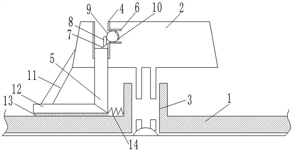
[0027] Embodiment 1 The reference signs in the accompanying drawings include: keyboard body 1, key 2, key hole 3, first through slot 4, slide bar 5, second through slot 6, retainer 7, push rod 8, air bag 9, Air outlet 10, support rod 11, brush plate 12, first bristles 13, spring 14.

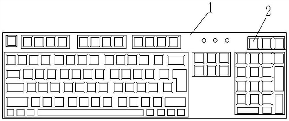
[0028] Such as figure 1 with figure 2 As shown, a self-cleaning keyboard includes a keyboard body 1 and buttons 2. Keyholes 3 are arranged on the keyboard body 1, and the buttons 2 are located on the keyholes 3. The upper surface of the buttons 2 is provided with a plurality of first through holes ( not shown in the figure), the inside of the button 2 is provided with a first through groove 4, the first through groove 4 is located at the top left of the button 2, the first through groove 4 communicates with the upper surface of the button 2, the inside of the first through groove 4 Connected with a slide bar 5, the slide bar 5 can slide up and down in the first slot 4, the height of the slide ...

Embodiment 2

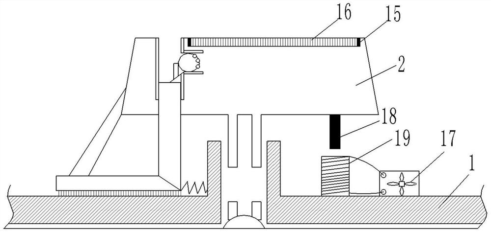
[0033] Embodiment 2 The reference numerals in the drawings also include: ventilation plate 15 , second bristles 16 , electric fan 17 , magnet 18 , and electromagnetic induction coil 19 .

[0034] Such as image 3 As shown, a self-cleaning keyboard, the difference between this embodiment and Embodiment 1 is: the inner lower surface of the key 2 is bonded with a ventilation plate 15, and the area of ​​the upper surface of the ventilation plate 15 is slightly smaller than the area of ​​the upper surface of the key 2. A number of second bristles 16 are adhered to the upper surface of the ventilation plate 15, and the part of the upper surface of the ventilation plate 15 that is not bonded with the second bristles 16 is a through hole. The gas passes through the ventilation plate 15 and is blown out from the first through hole of the key 2, the second bristles 16 will swing with the wind, and the oscillating second bristles 16 will clean the keys 2 of dust, and the gas will blow th...


PUM


Abstract

The invention relates to the technical field of computer keyboards, and specifically discloses an automatic cleaning keyboard, which includes a keyboard body and keys, and a first through groove is arranged inside the key, the first through groove communicates with the upper surface of the key, and the inside of the first through groove is connected There is a slide bar, and the lower end of the slide bar is set in a wedge shape; the side of the first through groove is connected with a second through groove, and the lower end of the connecting port of the two through grooves is hinged with a stopper, and the upper surface of the stopper is provided with a The push rod of the connection port, the inside of the second channel is equipped with an air bag, one side of the air bag is connected to the push rod, and the other side is provided with an air outlet; the side surface of the button is hinged with an inclined strut, and the lower end of the strut A brush plate is connected, and the lower surface of the brush plate is provided with first bristles in contact with the keyboard body. One side end of the brush plate is wedge-shaped to fit the slide bar, and the side end is connected to the key hole through a spring. This solution can not only clean the dust inside the keyboard when the keys are pressed, but also slow down the sweating of the hands.

Description

technical field [0001] The invention relates to the technical field of computer keyboards, in particular to an automatic cleaning keyboard. Background technique [0002] The keyboard is the most commonly used and most important input device, through which English letters, numbers, punctuation marks, etc. can be input into the computer, so as to issue commands and input data to the computer. During the input process, the sweat stains on the fingers will adhere to the surface of the keyboard, making the keys on the keyboard greasy after use. When the keyboard is put on hold, the dust in the air will be adsorbed on the keys and will fall into the gaps between the adjacent keys. [0003] The patent document with the Chinese patent publication number CN105931910A discloses a self-cleaning keyboard. The key includes a button and a keyway. It is made of a mesh curved plate; the keyway is vertically fixed on the bottom plate; on the inner wall of the keyway is installed a sensor c...

Claims


Application Information

Patent Timeline
Patent Type & Authority Patents(China)
IPC IPC(8): G06F3/02B08B5/02B08B1/00
CPCB08B1/002B08B5/02G06F3/0202
Inventor 任宏伟
Owner 深圳银宸科技有限公司
Why Eureka
Try Eureka