
Organic light-emitting display panel and display device

A light-emitting display, organic technology, applied to semiconductor devices, electrical components, circuits, etc., can solve the problems of decreased touch accuracy of organic light-emitting display panels, affecting the touch performance of organic light-emitting display panels, unstable cathode OL2 potential, etc. The effect of improving touch performance, improving display effect, and improving work performance

Active Publication Date: 2018-08-24
SHANGHAI TIANMA MICRO ELECTRONICS CO LTD
View PDF6 Cites 9 Cited by
  • Summary
  • Abstract
  • Description
  • Claims
  • Application Information

AI Technical Summary

Problems solved by technology

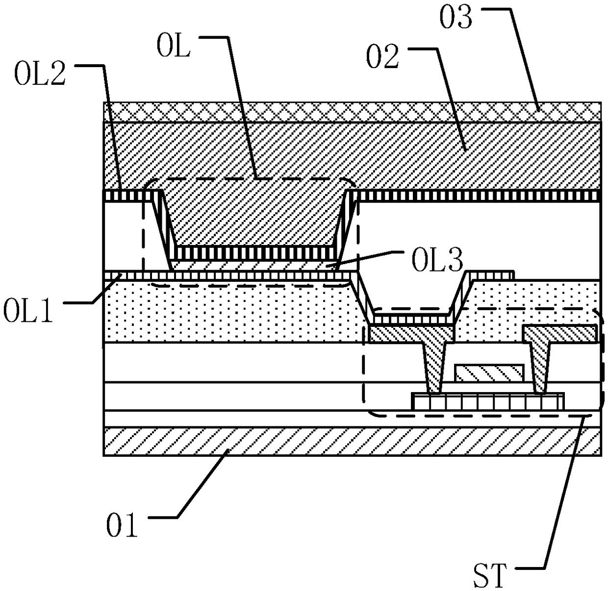
However, when the organic light-emitting display panel is working, the potential of the cathode OL2 is affected by the internal structure of the organic light-emitting display panel, and the potential of the cathode OL2 is unstable.
[0005] When the organic light emitting display panel is working, since the distance between the touch electrode layer 03 and the cathode OL2 is relatively close, when the potential of the cathode OL2 is unstable, the touch signal of the touch electrode layer 03 is disturbed, resulting in the failure of the organic light emitting display panel. The touch accuracy drops, and in serious cases, there will be random reporting, which affects the touch performance of the organic light-emitting display panel

Method used


Image

  • Organic light-emitting display panel and display device
  • Organic light-emitting display panel and display device
  • Organic light-emitting display panel and display device

Examples


Embodiment Construction

[0027] Various exemplary embodiments of the present invention will now be described in detail with reference to the accompanying drawings. It should be noted that the relative arrangements of components and steps, numerical expressions and numerical values ​​set forth in these embodiments do not limit the scope of the present invention unless specifically stated otherwise.

[0028] The following description of at least one exemplary embodiment is merely illustrative in nature and in no way taken as limiting the invention, its application or uses.

[0029] Techniques, methods and devices known to those of ordinary skill in the relevant art may not be discussed in detail, but where appropriate, such techniques, methods and devices should be considered part of the description.

[0030] In all examples shown and discussed herein, any specific values ​​should be construed as exemplary only, and not as limitations. Therefore, other instances of the exemplary embodiment may have dif...


PUM

PropertyMeasurementUnit
Widthaaaaaaaaaa

Abstract

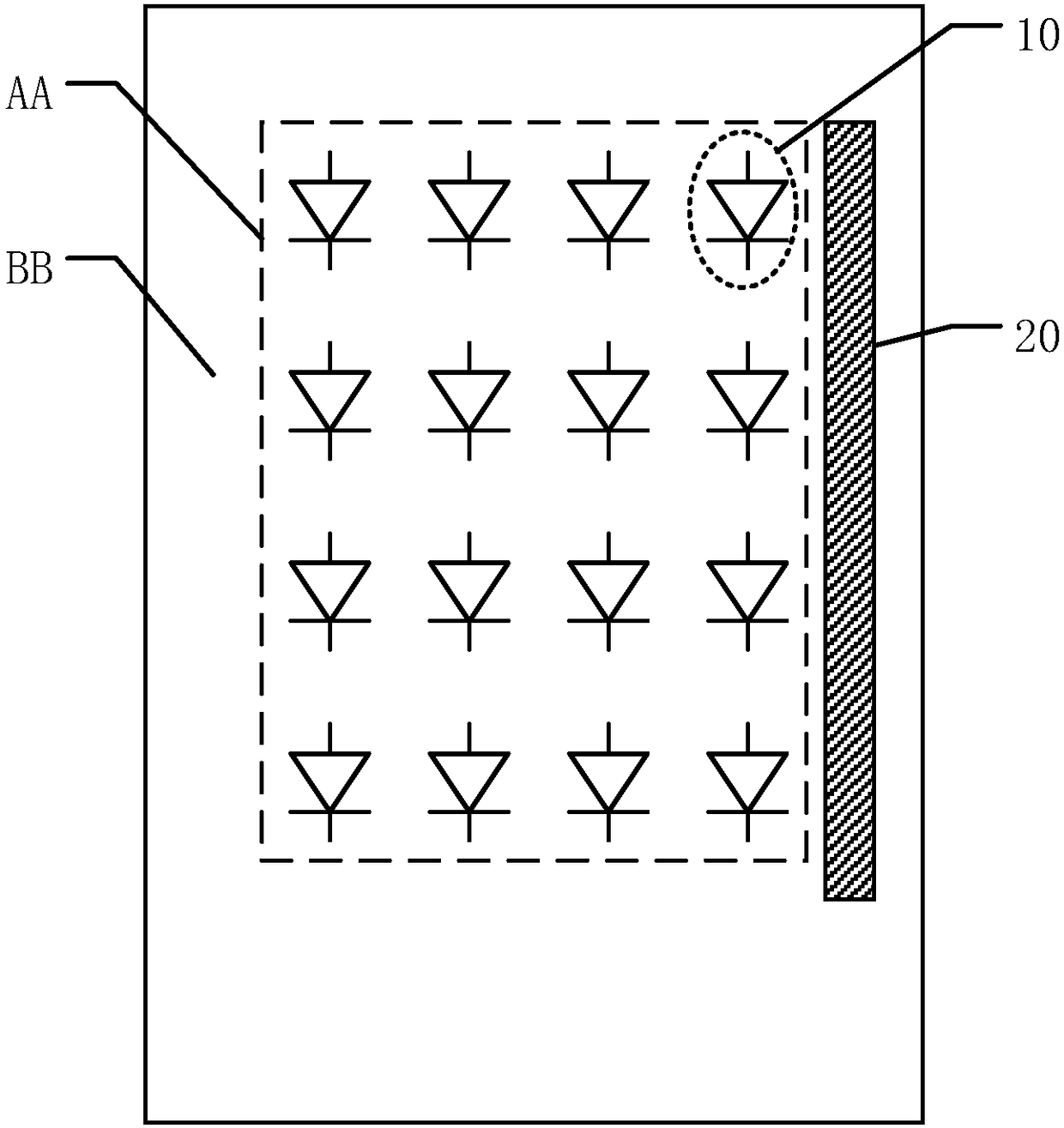
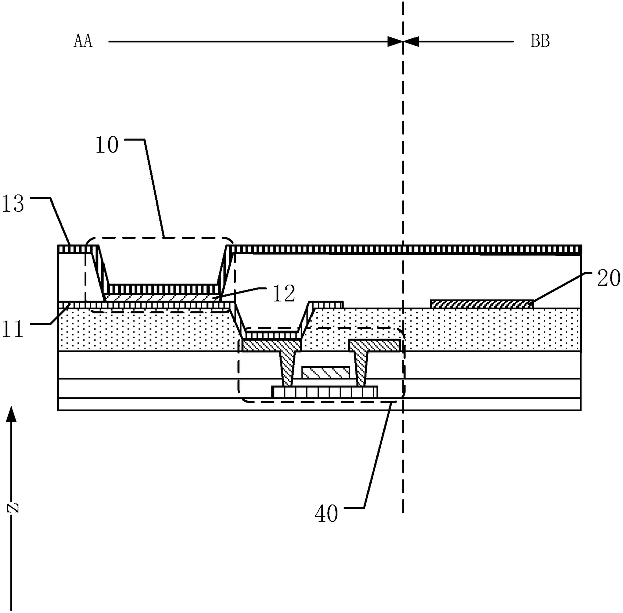
The invention discloses an organic light-emitting display panel and a display device, and belongs to the technical field of display. The display panel comprises a display area and a non-display area.The display panel comprises a plurality of organic light-emitting diodes, and each organic light-emitting diode comprises an anode, a light-emitting material part, and a cathode. The cathodes are arranged on the whole plane, and cover the display region and extend to the non-display region. The non-display region comprises at least one conductive part, and the conductive part receives a fixed voltage. At least some conductive parts are overlapped with the cathodes in an insulated manner in a direction perpendicular to the organic light-emitting display panel, and the conductive parts are insulated with the anodes. According to the invention, the organic light-emitting display panel is provided with the conductive parts, and the conductive parts are overlapped with the cathodes so as to form a storage capacitor, thereby enabling the electric potentials of the cathodes not to change abruptly. Compared with the prior art, the electric potentials of the cathodes remain relatively stable, thereby facilitating the improvement of the working performances of the plurality of organic light-emitting diodes, reducing the impact on an electric signal of a touch electrode from the instability of the electric potentials of the cathodes, and improving the touch performances.

Description

technical field [0001] The present invention relates to the field of display technology, and more specifically, to an organic light emitting display panel and a display device. Background technique [0002] In an organic light emitting display panel provided in the prior art, an organic light emitting diode (Organic Light Emitting Diode, OLED for short) is used as a light emitting unit. OLED display technology has the advantages of self-illumination, wide viewing angle, almost infinitely high contrast, low power consumption, and extremely high response speed. Organic light-emitting display panels are favored by consumers and are one of the important research and development directions of display technology. [0003] Please refer to figure 1 , the organic light emitting display panel provided by the prior art includes: a base substrate 01, a thin film transistor ST and an organic light emitting diode OL disposed on the base substrate 01, and an encapsulation layer 02 coveri...

Claims


Application Information

Patent Timeline
IPC IPC(8): H01L27/32
CPCH10K59/40H10K59/12
Inventor 丁洪马从华杜凌霄
Owner SHANGHAI TIANMA MICRO ELECTRONICS CO LTD
Features
  • Generate Ideas
  • Intellectual Property
  • Life Sciences
  • Materials
  • Tech Scout
  • Unparalleled Data Quality
  • Higher Quality Content
  • 60% Fewer Hallucinations
Learn More