
Charging gun head and charging system

A charging system and power terminal technology, which is applied to circuits, electrical components, coupling devices, etc., can solve the problems of manual charging, such as high labor intensity, increased volume and cost, and difficult operation with both hands, and achieve simple structure, reduced labor intensity, and reduced cost effect

Active Publication Date: 2018-08-24
SHANGHAI ZHIDA TECHNOLOGY DEVELOPMENT CO LTD
View PDF6 Cites 6 Cited by
  • Summary
  • Abstract
  • Description
  • Claims
  • Application Information

AI Technical Summary

Problems solved by technology

The development of fast charging technology makes the charging faster and faster. However, due to the thickening of the cable and the power terminal of the charging gun, the plugging force of the charging gun head is also increasing. At present, it is difficult to operate with both hands. The 80A DC charging gun For example, the overall insertion force is greater than 25KG, and the labor intensity of manual charging is relatively high
To overcome such a plug-in force during fast charging, the automatic charging system needs to have a suitable high-power mechanical arm, which brings about a substantial increase in size and cost

Method used


Image

  • Charging gun head and charging system
  • Charging gun head and charging system
  • Charging gun head and charging system

Examples


Embodiment 1

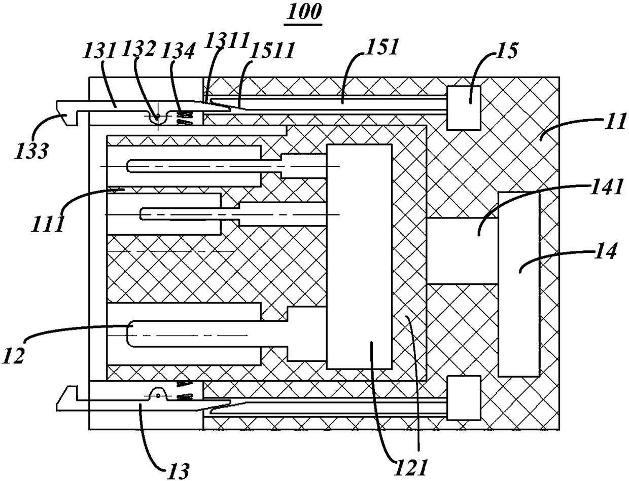
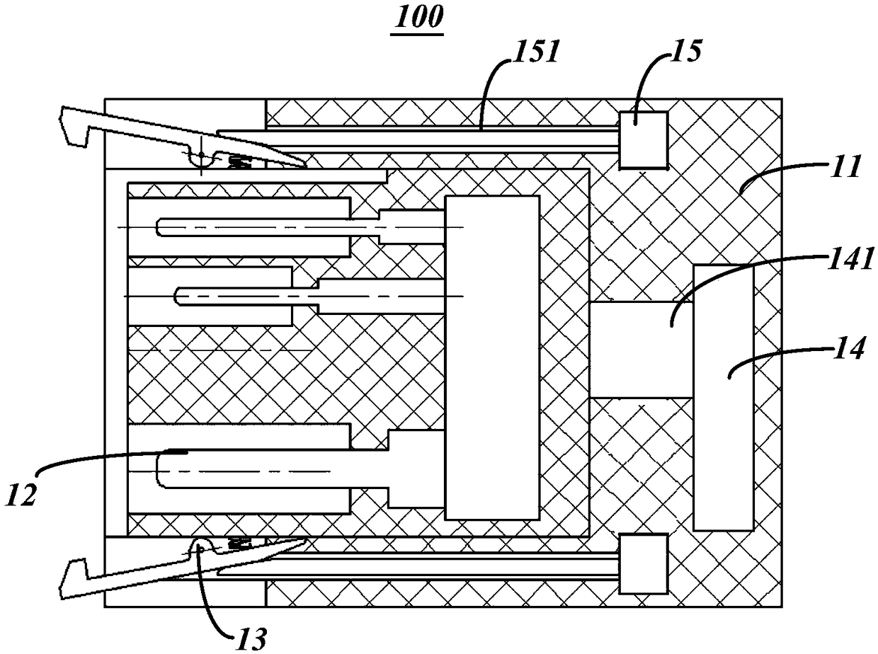
[0035] ginseng figure 1 As shown, the charging gun head 100 in this embodiment includes a gun head body 11 and a number of power terminals 12 located in the gun head body. Mechanism 13, the power terminal 12 is movable in the plug body 11 along the plugging direction, the rear end of the power terminal 12 is provided with a gun head drive module 14 for controlling the movement of the power terminal along the plugging direction, when the locking mechanism 13 is in the In the locked state, the gun head driving module 14 drives the power terminal 12 to move along the plugging and unplugging direction.

[0036] In this embodiment, the plugging direction is defined as the left-right direction, the insertion direction is along the extension direction of the terminal, and the extraction direction is the opposite direction of the insertion direction.

[0037] Preferably, a locking drive module 15 is provided at the rear end of the locking mechanism 13, the locking driving module 15 i...

Embodiment 2

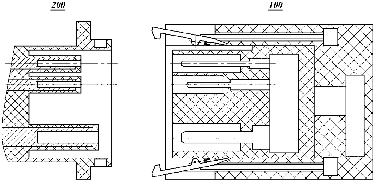
[0051] ginseng image 3 As shown, this embodiment discloses a charging system, including a charging gun head 100 and a charging socket 200 plugged into the charging gun head. The charging gun head 100 in this embodiment is completely the same as the charging gun head in Embodiment 1, and will not be repeated here.

[0052] combine Figure 4 As shown, the charging socket 200 in this embodiment includes a socket body 21 and a socket terminal 22 fixedly installed in the socket body 21 , and the socket terminal 22 is formed with a terminal receiving cavity 221 toward the direction of the charging gun head.

[0053] A locking slot 211 is provided at the end of the socket body 21 , and the buckle 133 on the locking mechanism 13 is fixed and locked in the locking slot 211 .

[0054] Preferably, a plurality of positioning accommodation cavities 212 are formed in the socket body 21 toward the direction of the charging gun head for accommodating the gun head positioning cavities 111 o...


PUM


Abstract

The invention discloses a charging gun head and a charging system. The charging gun head comprises a gun head body and a plurality of power supply terminals positioned inside the gun head body, wherein a plurality of locking mechanisms for being matched with external sockets are arranged at the end of the gun head body; the power supply terminals are arranged movably along the plugging direction inside the gun head body; a gun head drive module for controlling the power supply terminals to move along the plugging direction is arranged at the rear ends of the power supply terminals; and when the locking mechanism are in a locking state, the gun head drive module is used for driving the power supply terminals to move along the plugging direction. The charging gun head and the charging sockets are simple in structures, the plugging force can be reduced through the design of the charging gun head, the labor intensity is reduced, or the power of a charging mechanical arm is reduced greatly,and the cost of the charging system is reduced.

Description

technical field [0001] The invention relates to the technical field of electric vehicle charging equipment, in particular to a charging gun head and a charging system. Background technique [0002] With the rapid development of electric vehicles, electric vehicles are rapidly popularizing, fast charging of electric vehicles has become the focus of the development of the automobile industry and the energy industry, and fast charging technology has also emerged as the times require. The development of fast charging technology makes the charging faster and faster. However, due to the thickening of the cable and the power terminal of the charging gun, the plugging force of the charging gun head is also increasing. At present, it is difficult to operate with both hands. The 80A DC charging gun For example, the overall insertion force is greater than 25KG, and the labor intensity of manual charging is relatively high. For fast charging, to overcome such a plugging force, the auto...

Claims


Application Information

Patent Timeline
Patent Type & Authority Applications(China)
IPC IPC(8): H01R13/502H01R13/627H01R13/629
CPCH01R13/502H01R13/6275H01R13/629
Inventor 徐漫洋
Owner SHANGHAI ZHIDA TECHNOLOGY DEVELOPMENT CO LTD
Learn More