Modulation ring of modulated permanent magnet gear and manufacturing method thereof

A technology for modulating rings and gears, which is applied to permanent magnet clutches/brakes, manufacturing motor generators, electric brakes/clutches, etc. It can solve the problems affecting the rigidity and reliability of the overall structure, and the complexity of the manufacturing process of the modulating rings. Compact and ingenious, high-fit effect

Pending Publication Date: 2018-08-24
盐城永安科技有限公司
View PDF12 Cites 0 Cited by
  • Summary
  • Abstract
  • Description
  • Claims
  • Application Information

AI Technical Summary

Problems solved by technology

However, the current modulating ring manufacturing process is relatively complicated, the announcement number CN106452002A, the announcement date is February 22, 2017, the invention patent and announcement number CN205195533U named "Concentric Permanent Magnetic Gear Magnetic Adjustment Ring Device and Its Manufacturing Method", the announcement date On April 27, 2016, the utility model patent titled "Modulation Ring for Modulated Permanent Magnetic Gear" was relatively simple and easy to manufacture, but it was assembled by fastening and fixing with support pins or connecting screws and nuts, so It is necessary to perforate the end ring, which will affect the stiffness and reliability of the overall structure

Method used


Image

  • Modulation ring of modulated permanent magnet gear and manufacturing method thereof
  • Modulation ring of modulated permanent magnet gear and manufacturing method thereof
  • Modulation ring of modulated permanent magnet gear and manufacturing method thereof

Examples


specific Embodiment approach 1

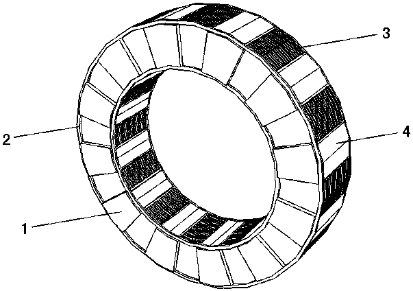
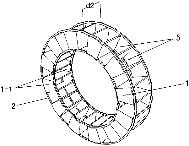
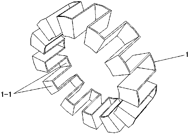
[0019] Specific implementation mode one: as Figure 1~Figure 6 As shown, the present invention discloses a modulating ring of a modulated permanent magnet gear, which includes a main body component 1, two end rings 2, a plurality of magnetically permeable components 3 and a plurality of non-magnetically permeable components 4, the main component 1 It is a cylindrical member formed by multiple alternate folds on both sides of the annular plate. The open end of each fold communicates with the corresponding end surface of the main body member 1 to form a ∏-shaped fold body 1-1. A plurality of the above-mentioned ∏-shaped folds 1-1 are equiangularly staggered along the circumferential direction of the main body member 1, and the opening directions of every two adjacent ∏-shaped folds 1-1 are opposite, and the middle positions of the two end rings 2 are equiangular along the circumferential direction respectively. A plurality of openings 2-4 are provided, and the plurality of openi...

specific Embodiment approach 2

[0020] Specific implementation mode two: as figure 2 , 4 As shown, this embodiment is a further description of Embodiment 1. Each of the end rings 2 includes an outer ring 2-1, an inner ring 2-2 and a plurality of fan-shaped separators 2-3. The outer ring 2-1 and the inner ring 2-2 are coaxially arranged, and the plurality of fan-shaped separators 2-3 are equally spaced around in a ring shape and arranged between the outer ring 2-1 and the inner ring 2-2 In between, the outer ring 2-1 and the inner ring 2-2 are welded and fixed by a plurality of fan-shaped separators 2-3, and the communication opening 2-4 is formed between every two adjacent fan-shaped separators 2-3.

specific Embodiment approach 3

[0021] Specific implementation mode three: as figure 1 , 5 As shown, this embodiment is a further description of Embodiment 1 or Embodiment 2. Each of the magnetic permeable members 3 is formed by stacking a plurality of silicon steel sheets 3 - 1 along the axial direction of the main body member 1 .


PUM


Abstract

The invention provides a modulation ring for a modulated permanent magnet gear and a manufacturing method thereof, relating to a modulation ring and a manufacturing thereof. A main body member is a cylindrical member which is formed by alternately folding two sides of an annular plate, and each fold opening end and a corresponding end face of the main body member are in communication to form an n-shaped fold body. Multiple n-shaped fold bodies are alternately arranged with the same angle along the circumferential direction of the main body member, and the opening directions of each two adjacent n-shaped fold bodies are opposite. Two end rings are provided with a plurality of ports which are matched with multiple n-shaped fold body closed ends of the main body member at the same end, the two end rings are coaxially spaced between the multiple n-shaped fold bodies of the main body member, each of the n-shaped fold bodies separates the space between the annular surfaces of the two end rings into a fan-shaped mounting groove, and each magnetically permeable member or non-magnetically-permeable member is in interference fit with a corresponding fan-shaped mounting groove. The form of assembly is adopted, and the rigidity and reliability are guaranteed to a greater extent while the manufacturing is simple.

Description

technical field [0001] The invention relates to a modulating ring and a manufacturing method thereof, in particular to a modulating ring of a modulating permanent magnet gear and a manufacturing method thereof. Background technique [0002] Permanent magnet gears use magnetic transmission, so there is no mechanical contact between the gears, and it is precisely because the meshing between permanent magnet gears has no contact, no friction energy consumption, and smooth transmission, which reflects the high efficiency and reliability of permanent magnet gears. The advantages of high, low noise and long service life. Secondly, it does not need lubrication, cleanness, no oil, dustproof and waterproof, etc., and it has the function of overload protection, and it can cut off the transmission relationship at any time when overloaded, so it is widely used. [0003] The current modulated permanent magnet gear generally consists of an outer rotor, an inner rotor and a modulation rin...

Claims


Application Information

Patent Timeline
IPC IPC(8): H02K49/10H02K15/00
CPCH02K15/00H02K49/102
Inventor 于广滨毛汉成张元
Owner 盐城永安科技有限公司
Why Eureka
Try Eureka