Eureka AIR delivers breakthrough ideas for toughest innovation challenges, trusted by R&D personnel around the world.

Sink dishwasher panel with spraying arms

A dishwashing machine and spray arm technology, applied in the direction of tableware washing machine/rinsing machine, tableware washing machine/rinsing and rinsing machine parts, cleaning equipment, etc., can solve the problem of bacteria unfavorable to the cleanliness of the sink dishwasher and maintain the cleaning process Frequent, affecting customer experience and other problems, to achieve the effect of concealed and reliable structure, reduce spray dead angle, and good spray effect

Pending Publication Date: 2018-08-28
NINGBO MEIGAO KITCHENWARE CO LTD
View PDF12 Cites 0 Cited by
  • Summary
  • Abstract
  • Description
  • Claims
  • Application Information

AI Technical Summary

Problems solved by technology

And the existing sink dishwasher often installs the spray arm at the bottom of the sink, and the dishes on the dish rack are cleaned by the high-pressure water column produced by the spray arm, but the sink dishwasher of this prior art often has The following problems are as follows: first, the spray arm should spray upwards, so its water column needs to overcome its own gravity, so the required water pressure is high; second, the naturally falling water droplets will collide with the upward sprayed water column. Third, when the oil stains on the dishes fall into the sink with the water column, they will adhere to the spray arm. During long-term use, the spray arm and the dishwashing The accumulation of dead corners in the tank is not only easy to breed bacteria, which is not conducive to the cleanliness of the sink dishwasher, but also requires frequent maintenance and cleaning processes, which affects customer experience

Method used


Image

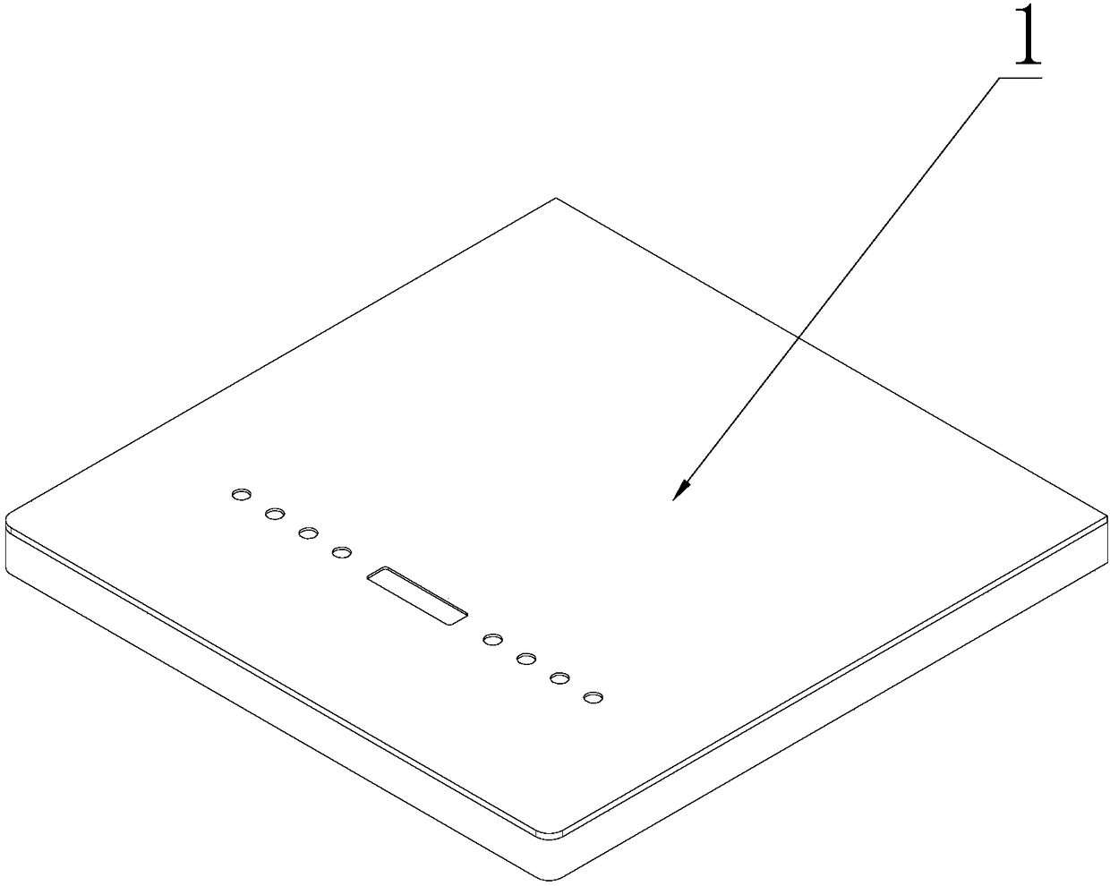
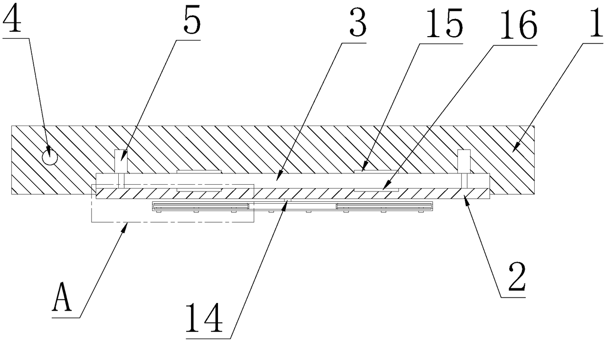
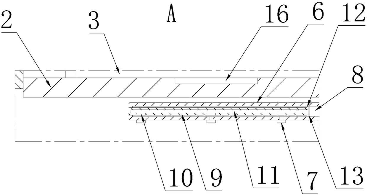
  • Sink dishwasher panel with spraying arms
  • Sink dishwasher panel with spraying arms
  • Sink dishwasher panel with spraying arms

Examples


Embodiment Construction

[0019] The present invention will be further described below in conjunction with the accompanying drawings and specific embodiments.

[0020] The present invention provides a sink dishwasher panel with a spray arm, which includes a panel body 1, the lower end surface of the panel body 1 is provided with a mounting groove, and a movable block 2 is placed in the mounting groove, and the movable block 2 is arranged along the vertical direction. Slidingly fit with the installation groove, and the side wall of the movable block 2 is attached to the inner side wall of the installation groove, so that the upper end surface of the movable block 2 and the inner surface of the installation groove are enclosed to form a closed working chamber 3, the The panel body 1 is provided with a water inlet pipe 4 for supplying the water flow of the working chamber 3. The panel body 1 is located above the movable block 2 and is provided with a plurality of hydraulic cylinders 5 arranged at intervals...


PUM


Abstract

The invention discloses a sink dishwasher panel with spraying arms. The panel comprises a panel body, a mounting groove is formed in the lower end face of the panel body, a movable block is containedin the mounting groove, and a working cavity is defined by the upper end face of the movable block and the inner surface of the mounting groove; the panel body is provided with a water inlet pipe, a plurality of hydraulic cylinders are arranged at the portion, located above the movable block, in the panel body in the horizontal direction at intervals, and piston rods of the hydraulic cylinders penetrate through the working cavity and are fixedly connected with the upper end face of the movable block; the main spraying arm is mounted on the lower end face of the movable block, a plurality of spraying nozzles are arranged on the lower end face of the main spraying arm in the horizontal direction at intervals, the main spraying arm is internally provided with a water supply pipeline, and thewater supply pipeline is communicated with the working cavity through a connection pipeline in the movable block. According to the sink dishwasher panel with the spraying arms, the spraying arms are directly mounted on the panel, so that not only is the spraying effect is good, but also oil stains on dishes are not easily attached to the spraying arms.

Description

technical field [0001] The invention relates to the technical field of sink dishwashers, in particular to a sink dishwasher panel with a spray arm. Background technique [0002] The sink dishwasher is a self-cleaning kitchen utensil integrated on the sink to realize the automatic cleaning of dishes, even fruits and vegetables. And the existing sink dishwasher often installs the spray arm at the bottom of the sink, and the dishes on the dish rack are cleaned by the high-pressure water column produced by the spray arm, but the sink dishwasher of this prior art often has The following problems are as follows: first, the spray arm should spray upwards, so its water column needs to overcome its own gravity, so the required water pressure is high; second, the naturally falling water droplets will collide with the upward sprayed water column. Third, when the oil stains on the dishes fall into the sink with the water column, they will adhere to the spray arm. During long-term use, ...

Claims


Application Information

Patent Timeline
Patent Type & Authority Applications(China)
IPC IPC(8): A47L15/42
CPCA47L15/4278Y02B40/00
Inventor 梅海滨
Owner NINGBO MEIGAO KITCHENWARE CO LTD
Why Eureka
Eureka Blog
Learn More