Toy rocket and control method thereof

A rocket and toy technology, which is applied in the field of toy rockets and their control, can solve the problems of high power consumption, short working time of toy rockets, and limited battery storage capacity, and achieve the goals of reducing hardware costs, improving user experience, and shortening working hours Effect

Pending Publication Date: 2018-08-28
SHENZHEN YANGRI ELECTRONICS
View PDF7 Cites 9 Cited by
  • Summary
  • Abstract
  • Description
  • Claims
  • Application Information

AI Technical Summary

Problems solved by technology

[0005] When the existing toy airplanes are in use, the propellers continue to work after each takeoff, which consumes a lot of power. However, due to weight restrictions and limited battery storage capacity of general toy airplanes, the working time of toy rockets is very short.

Method used


Image

  • Toy rocket and control method thereof
  • Toy rocket and control method thereof
  • Toy rocket and control method thereof

Examples


Embodiment 1

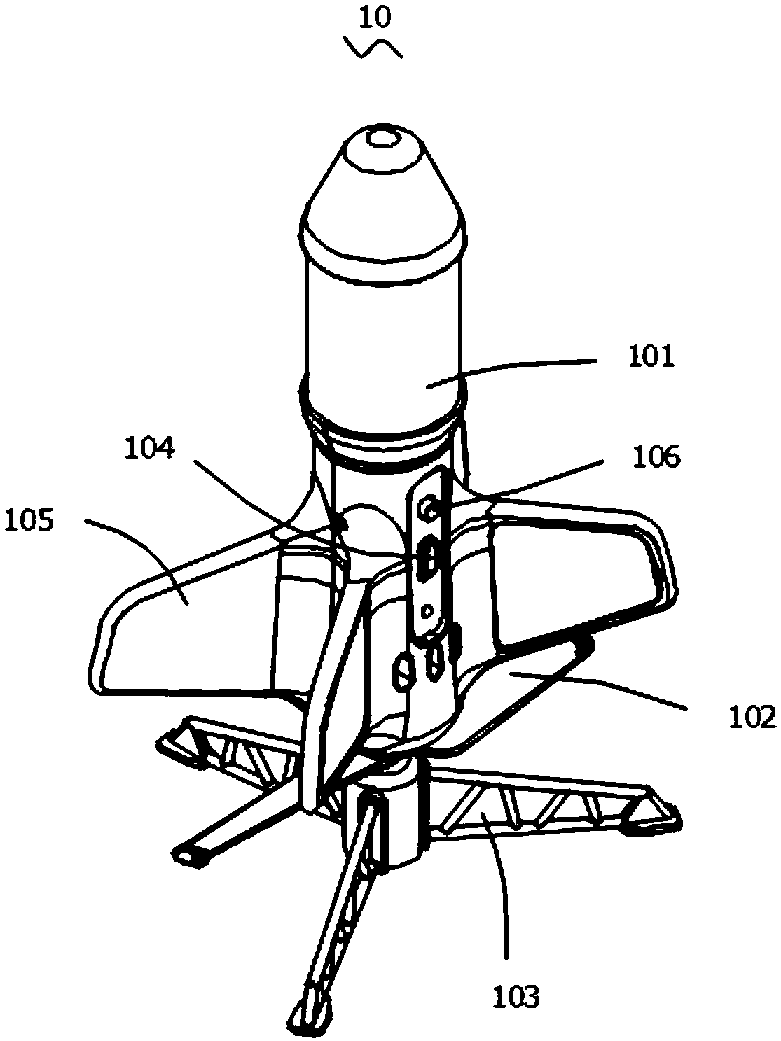
[0045] Please also refer to 1- Figure 4 , the present embodiment provides a toy rocket 10, comprising:

[0046] The fuselage 101 is in the shape of a rocket so that the toy rocket 10 can move forward in a straight line, and a control circuit 114 , a battery 115 and a first driving device 113 are arranged inside it.

[0047] The propeller 102 is located at the bottom of the fuselage 101, and the propeller 102 is connected to the first driving device 113 by transmission, so that the propeller 102 can push the fuselage 101 to rise vertically;

[0048] The bottom of the propeller 102 is also provided with a launcher 103. The launcher 103 is inserted into the central hole at the bottom of the propeller 102 through the short axis at the top and is movably connected to the propeller for supporting the fuselage 101 at the bottom before take-off. Can break away from launching stand 103 and take off, certainly also can not need launching stand 103, directly hold in hand and take off. ...

Embodiment 2

[0062] This embodiment provides a toy rocket 10 and its control method. Compared with Embodiment 1, the difference of this embodiment is:

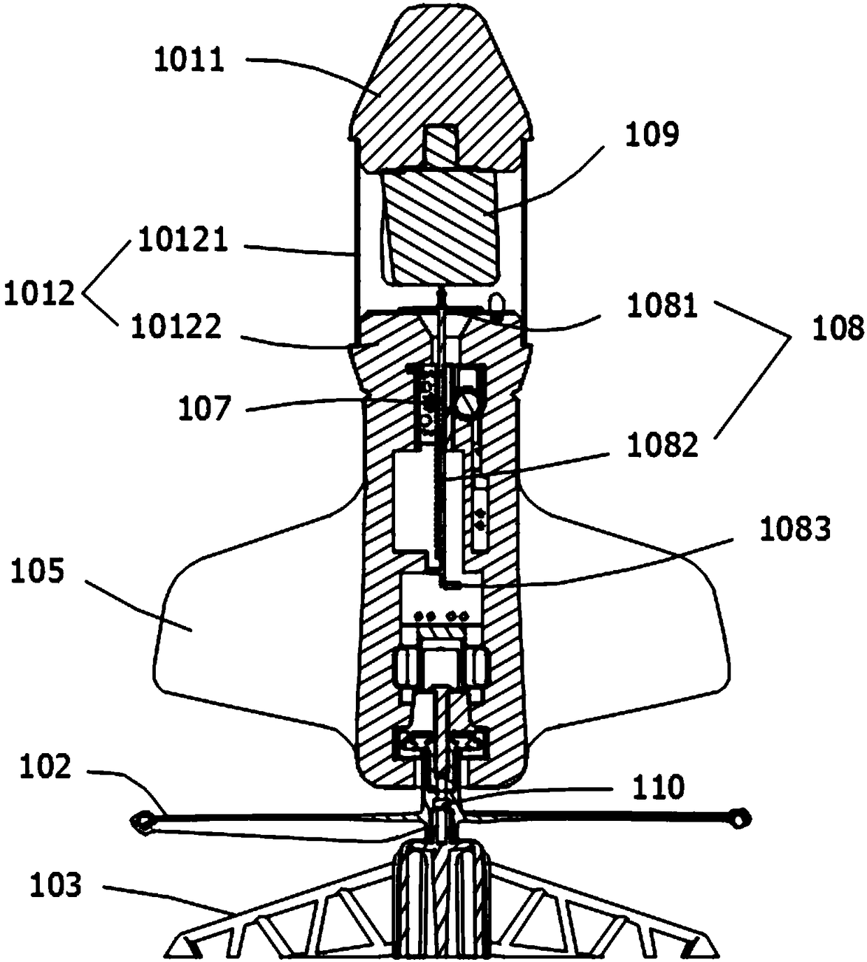
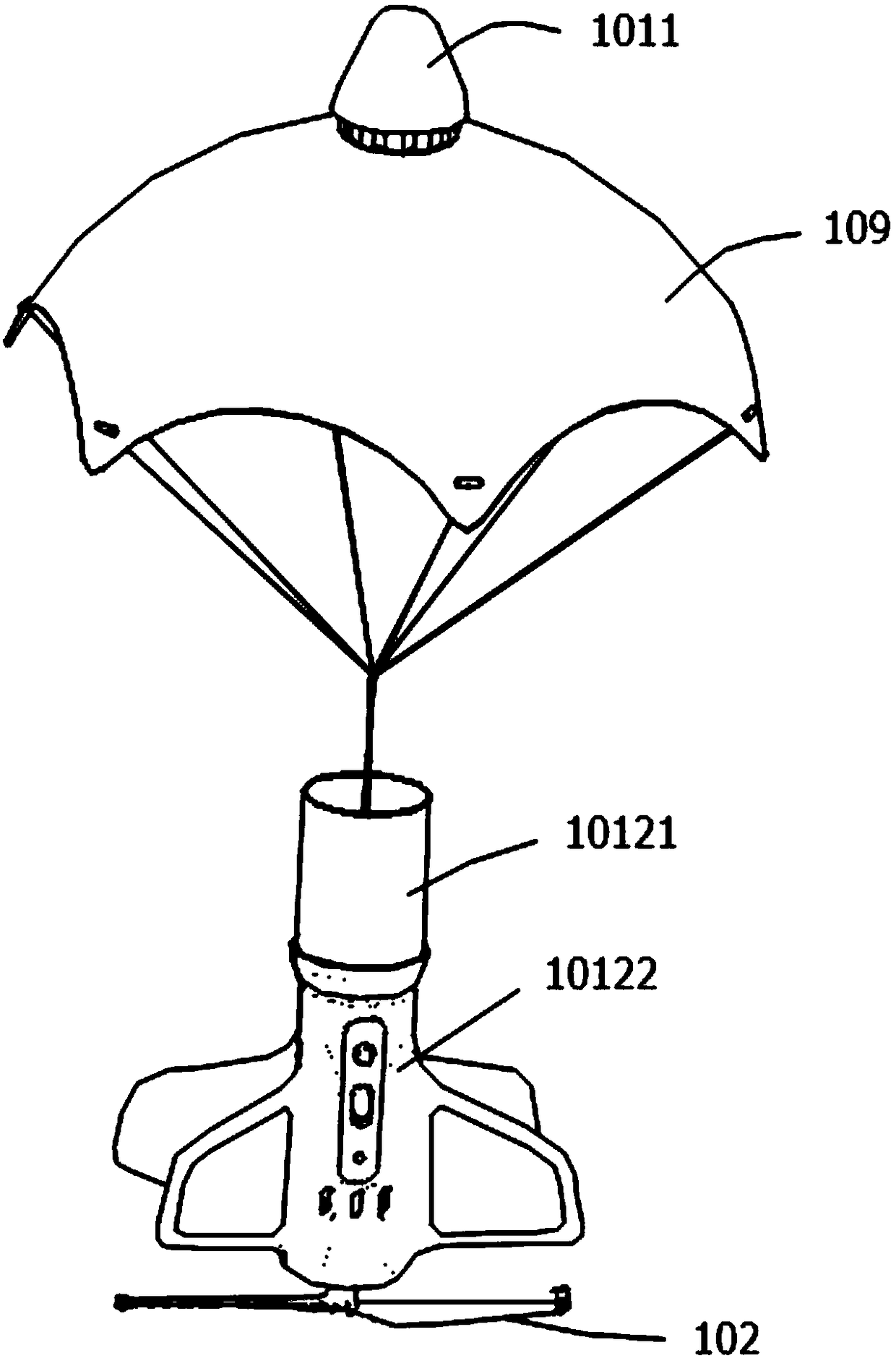
[0063] Such as Figure 5 As shown, in this embodiment, the second driving device includes an electromagnetic assembly, a pusher 108 and a spring, the electromagnetic assembly generates a magnetic force acting on the pusher 108, and the spring is held between the electromagnetic assembly and the pusher 108 in a pre-compressed state, The parachute of the parachute 109 is fixedly connected with the pusher 108 or the cabin body 1012 .

[0064] Preferably, the pusher 108 includes a push plate 1081 and a connecting rod 1084 connected as one, the push plate 1081 is positioned above the connecting rod 1084, the cabin body 1012 includes an equipment cabin 10122 and an umbrella cabin 10121 that communicate with each other, and the push plate 1081 is configured as It can generate magnetic force with the electromagnetic components, for example, the p...

Embodiment 3

[0068] This embodiment provides a toy rocket 10 and its control method. Compared with Embodiment 1, the difference of this embodiment is:

[0069] Such as Figure 6 As shown, in this embodiment, the second driving device includes a motor, and the output end of the motor is configured to be able to expand and contract in the vertical direction, and the parachute 109 is fixedly connected to the output end of the motor or the cabin body 1012 by the parachute rope.

[0070] Other features in this embodiment are the same as those in Embodiment 1 and will not be further described.


PUM


Abstract

The invention provides a toy rocket and a control method thereof. Propellers are located at the bottom of a rocket body, so that the upper portion of the rocket body is not occupied and other functional structures can be installed on the upper portion of the rocket body. The toy rocket can drop freely after taking off by the arrangement of a parachute, a remote controller is no longer a necessarytool of the toy rocket, the remote controller can be used for controlling the toy rocket to take off or the remote controller does not need to be used and the toy rocket takes off by directly turningon a switch on the toy rocket, hardware cost is reduced, real-time control of a user is not needed, the complicity of controlling is reduced and the user experience is improved. The working time of the propellers during each flight can be shortened to reduce electricity consumption, and the toy rocket can be used longer every time after the toy rocket is charged; the propellers are used during theblast-off stage of the toy rocket, and the parachute is used during the landing stage of the toy rocket, so that the toy rocket is capable of performing multiple actions to improve using interestingness, and the user experience is further improved.

Description

technical field [0001] The invention relates to the field of toys, in particular, to a toy rocket and a control method thereof. Background technique [0002] In recent years, with the development of technology, toy cars have been gradually replaced by toy airplanes. Common toy rockets include a body and a remote control. Among them, the body includes a propeller unit, a fuselage and a tripod. or multi-paddle. [0003] In the existing toy aircraft, the propeller is arranged on the upper part of the fuselage, so that the structural space of the upper part of the fuselage is limited, and it is difficult to use the upper part of the fuselage to install other functional structures. [0004] When the existing toy airplanes are in use, the hardware cost is increased due to the need for a remote controller to control them, and real-time control by the user is required, which increases the workload of the user and makes the user experience need to be improved. [0005] When the exi...

Claims


Application Information

Patent Timeline
Patent Type & Authority Applications(China)
IPC IPC(8): A63H27/00A63H27/14A63H29/22A63H30/04
CPCA63H27/005A63H27/14A63H29/22A63H30/04
Inventor 林日壮
Owner SHENZHEN YANGRI ELECTRONICS
Why Eureka
Try Eureka