Device and method for car-to-car charging
A vehicle-to-vehicle, charger technology, applied in circuit devices, battery circuit devices, electric vehicle charging technology, etc., can solve problems such as electric shocks for operators, and achieve the effect of cost saving and road rescue convenience.
- Summary
- Abstract
- Description
- Claims
- Application Information
AI Technical Summary
Problems solved by technology
Method used
Image
Examples
Embodiment 1
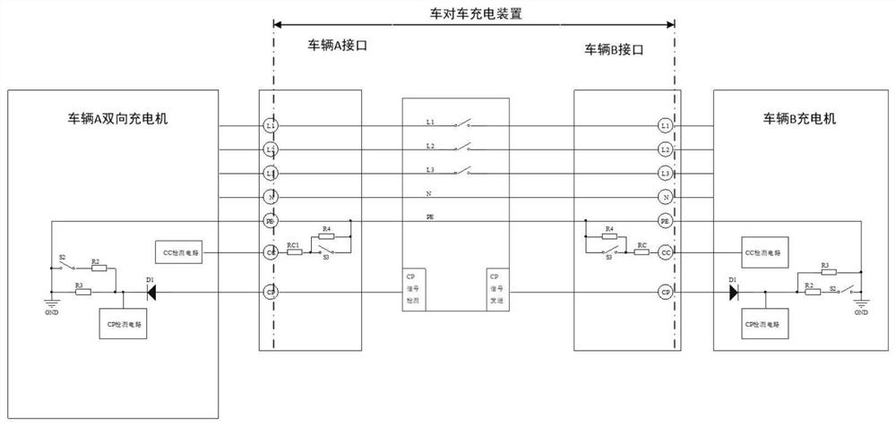
[0037] A vehicle-to-vehicle charging device, such as figure 1with figure 2 As shown, among them, figure 1 Shown car A is a power supply car, and car B is a tram receiving car. The vehicle-to-vehicle charging device includes: a vehicle-mounted bidirectional charger, a charging and discharging connection device and a control box.
[0038] The vehicle-mounted two-way charger is used to charge the electric vehicle or receive the discharge of the power supply vehicle. The vehicle-mounted two-way charger includes an inverter, a rectifier and a charge-discharge mode control unit, and the inverter is used to convert direct current into alternating current , so that the battery on the car provides output power for the on-board bidirectional charger. The rectifier is used to convert the alternating current into direct current to charge the battery on the car. The charging and discharging mode control unit is used to control the charging direction and switch The working mode of the o...
Embodiment 2
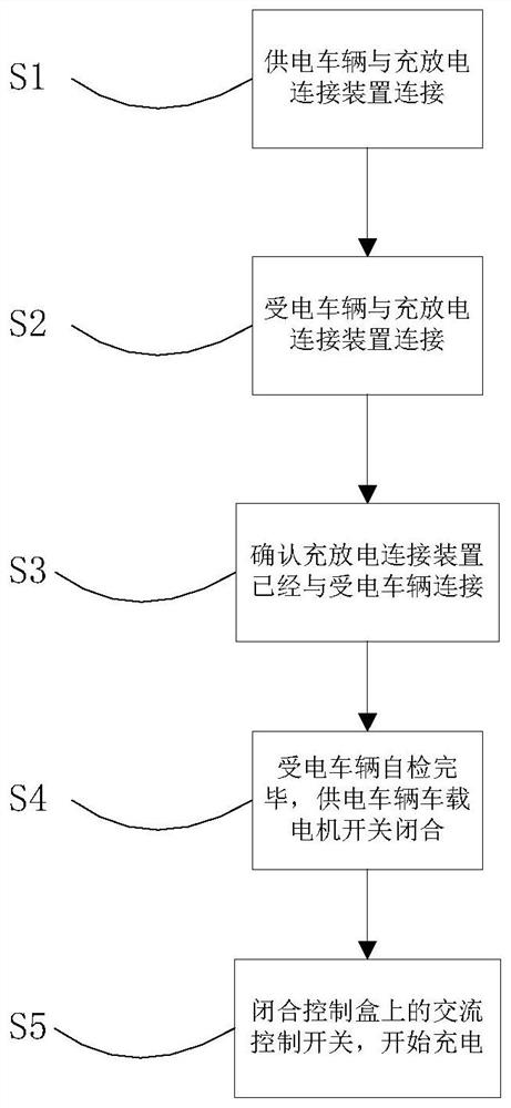
[0056] The embodiment of the present invention proposes a vehicle-to-vehicle charging method, such as image 3 As shown, the method includes:
[0057] S1. The first vehicle-mounted bidirectional charger of the power supply vehicle is connected to the charging and discharging connection device, and sends a CP signal and a CC signal to the second vehicle-mounted bidirectional charger of the powered vehicle. The CC signal is used for connection confirmation, and the CP signal is used for connection confirmation. confirmed by control
[0058] S2. The second on-board two-way charger of the receiving vehicle is connected to the charging and discharging connection device, and obtains the CP signal and CC signal from the charging and discharging connecting device. If the CC signal is successfully transmitted, the connection is confirmed, and the receiving vehicle starts self-inspection;
[0059] S3. After the CC signal line is turned on, the power supply vehicle adjusts the amplitude...
Embodiment 3
[0066] The embodiment of the present invention proposes a control box, the control box is set on the vehicle-to-vehicle charging and discharging connection device, the control box is used to access and control the signal sent by the power supply vehicle, and transmit the signal to the power receiving vehicle.
[0067] Such as Figure 4 As shown, car A is the power supply car, and car B is the electric car. The control box is provided with a power supply vehicle interface and an electric vehicle interface. The control box is also provided with a CP signal detection unit and a CP signal transmission unit. The CP signal detection unit is connected to one side of the power supply vehicle, and the CP signal The sending unit is connected to one side of the receiving car.
[0068] Both the power supply vehicle interface and the electric vehicle interface are equipped with a three-phase alternating current interface, an N line interface, a PE line interface, a CC signal interface an...
PUM
 Abstract
Description
Claims
Application Information
 - R&D
- Intellectual Property
- Life Sciences
- Materials
- Tech Scout
- Unparalleled Data Quality
- Higher Quality Content
- 60% Fewer Hallucinations
Browse by: Latest US Patents, China's latest patents, Technical Efficacy Thesaurus, Application Domain, Technology Topic, Popular Technical Reports.
© 2025 PatSnap. All rights reserved.Legal|Privacy policy|Modern Slavery Act Transparency Statement|Sitemap|About US| Contact US: help@patsnap.com


