Pre-bending construction method for steel-concrete combined girders

A construction method and pre-bending technology, applied in bridges, bridge materials, bridge construction and other directions, can solve the problems of vehicle traffic interference, temporary lifting heavy, imposing heavy objects, etc., and achieve the effects of convenient construction, simple construction and simple principle.

Active Publication Date: 2018-08-28
GUANGZHOU MUNICIPAL ENG DESIGN & RES INST CO LTD
View PDF7 Cites 5 Cited by
  • Summary
  • Abstract
  • Description
  • Claims
  • Application Information

AI Technical Summary

Problems solved by technology

In China, temporary lifting lugs are also set at the bottom of the beam end, and the pre-bent platform at the mid-span position is lifted by steel wire rope, and then temporary lifting weight is applied to the bottom of the pre-bending platform and the bracket is placed on the pre-bending platform, and the temporary lifting weight is gradually removed. The rebound force exerts a pre-bending force on the steel beam through the sand box. This process avoids the erection of temporary supports, but to achieve a reasonable pre-bending force, the required temporary lifting weight is also very large. At this time, the elastic elongation of the steel wire rope is very large. It is large and needs to be loaded with heavy objects, which will cause greater interference to the passage of vehicles under the bridge, and is not suitable for cross-river bridges

Method used


Image

  • Pre-bending construction method for steel-concrete combined girders
  • Pre-bending construction method for steel-concrete combined girders
  • Pre-bending construction method for steel-concrete combined girders

Examples


Embodiment Construction

[0030] refer to Figure 1 to Figure 6 , which shows the specific structure of the preferred embodiment of the present invention. The structural characteristics of each component of the present invention will be described in detail below.

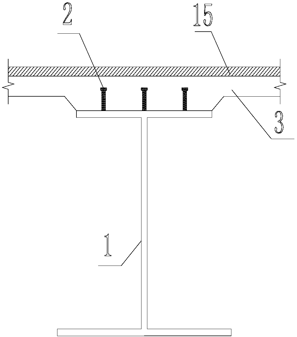
[0031] The steel-concrete combined girder bridge structure includes a steel girder 1 , a concrete bridge deck 3 , a shear connector 2 and a bridge deck pavement 15 .

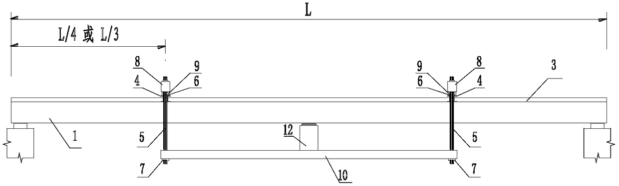
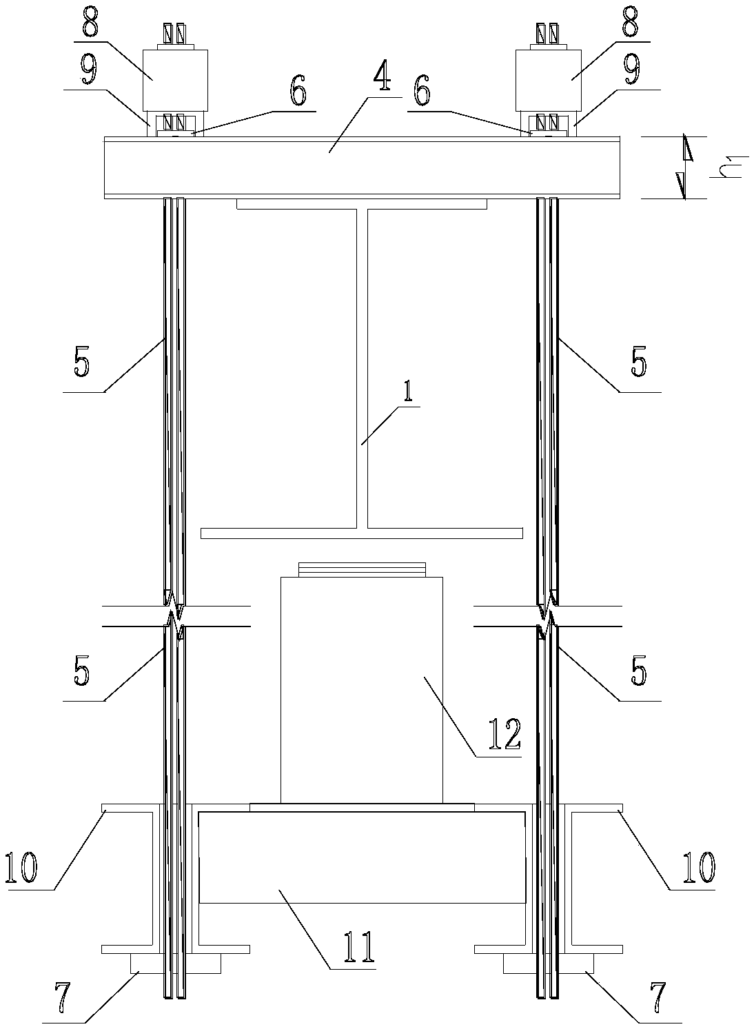
[0032] The present invention provides a steel-concrete combined girder bridge pre-bending structure, comprising a steel girder 1, a pre-bending beam 10 arranged below the steel girder 1 along the longitudinal direction of the bridge, and a pre-bending beam 10 arranged between the pre-bending beam 10 and the steel girder 1 The pre-bending support 12, between the pre-bending beam 10 and the steel beam 1 is provided with a pre-bending tension member 5 on both sides of the pre-bending support 12, the pre-bending tension member 5 and / or pre-bending The supporting member 12 is pro...


PUM


Abstract

The invention discloses a pre-bending construction method for steel-concrete combined girders, and is applied to the technical field of bridge construction. The pre-bending construction method includes S10, mounting steel girders, arranging pre-bending girders below the steel girders along the vertical direction of bridge girders, and connecting two ends of the pre-bending girders to the steel girders through pre-bending and tensioning pieces directly or indirectly; S20, arranging pre-bending supports at midspan positions of the steel girders and on the pre-bending girders; S30, pre-bending the steel girders by tensioning the pre-bending and tensioning pieces and/or lifting the pre-bending supports; S40, pouring concrete on the steel girders to form concrete bridge faceplates. The pre-bending construction method has the advantages that the pre-bending girders are arranged below the bridge girders and are connected with the steel girders through the pre-bending and tensioning pieces, the pre-bending supports are arranged between pre-bending bridge spans and the steel girders, and pre-bending force is applied to the steel girders through the pre-bending and tensioning pieces at two ends of the pre-bending girders and/or pre-stressing force application pieces on the pre-bending supports, so that erection of temporary support frames (support piles) is avoided, passing of vehicles below bridges is not affected greatly, and great convenience is brought to construction.

Description

technical field [0001] The invention is used in the technical field of bridge construction, and in particular relates to a pre-bending construction method for a steel-concrete composite girder bridge. Background technique [0002] The construction of steel-concrete combined beam bridges is convenient and takes full advantage of the respective advantages of steel and concrete. It is widely used in medium and small-span bridges. For superimposed structures, it is usually necessary to set up temporary supports as the application points of the pre-bending force. The erection of temporary supports increases the engineering investment, and has high requirements on the geological conditions under the bridge, and sometimes needs to occupy the driveway under the bridge, so it has great limitations. In China, temporary lifting lugs are also installed at the bottom of the beam end, and the pre-bending platform at the mid-span position is lifted by steel wire ropes, and then temporary ...

Claims


Application Information

Patent Timeline
Patent Type & Authority Applications(China)
IPC IPC(8): E01D21/00E01D101/28
CPCE01D21/00E01D2101/285
Inventor 宁平华乐小刚王晟胡会勇罗永乐郭玉平周昱张松涛
Owner GUANGZHOU MUNICIPAL ENG DESIGN & RES INST CO LTD
Why Eureka
Try Eureka