Manual jacking pipe control method and control system

A control method and pipe jacking technology, which is applied in radio wave measurement system, satellite radio beacon positioning system, pipeline laying and maintenance, etc., can solve problems such as inability to monitor and adjust in time, pipeline direction deviation, etc., to shorten correction time, The effect of reducing overall cost and reducing difficulty

Active Publication Date: 2018-08-28
CHINA MCC5 GROUP CORP
View PDF6 Cites 2 Cited by
  • Summary
  • Abstract
  • Description
  • Claims
  • Application Information

AI Technical Summary

Problems solved by technology

[0005] The purpose of the present invention is to overcome the deficiencies of the prior art. The purpose is to provide an artificial pipe jacking control method and control system to solve the

Method used


Image

  • Manual jacking pipe control method and control system
  • Manual jacking pipe control method and control system
  • Manual jacking pipe control method and control system

Examples


Embodiment 1

[0035] like Figure 1-3 Shown, a kind of artificial pipe jacking control method of the present invention comprises steps:

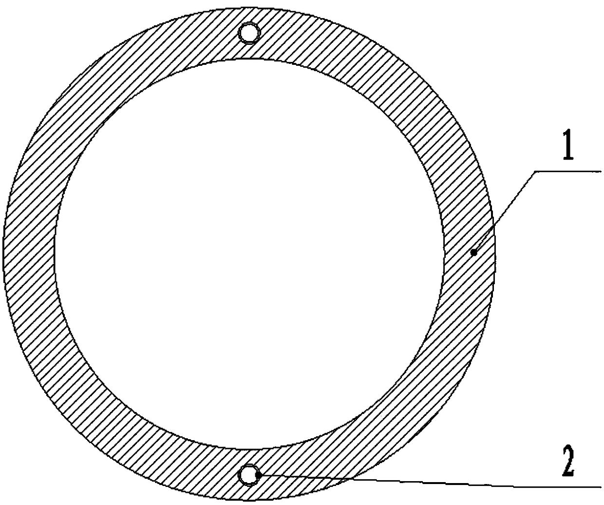
[0036] Step 1) There are two laser detection tubes 2 symmetrically in the tube wall of each cement concrete tube 1, and the laser detection tubes 2 can be formed by pre-embedded pipelines (seamless steel tubes), or can be formed by casting molds;

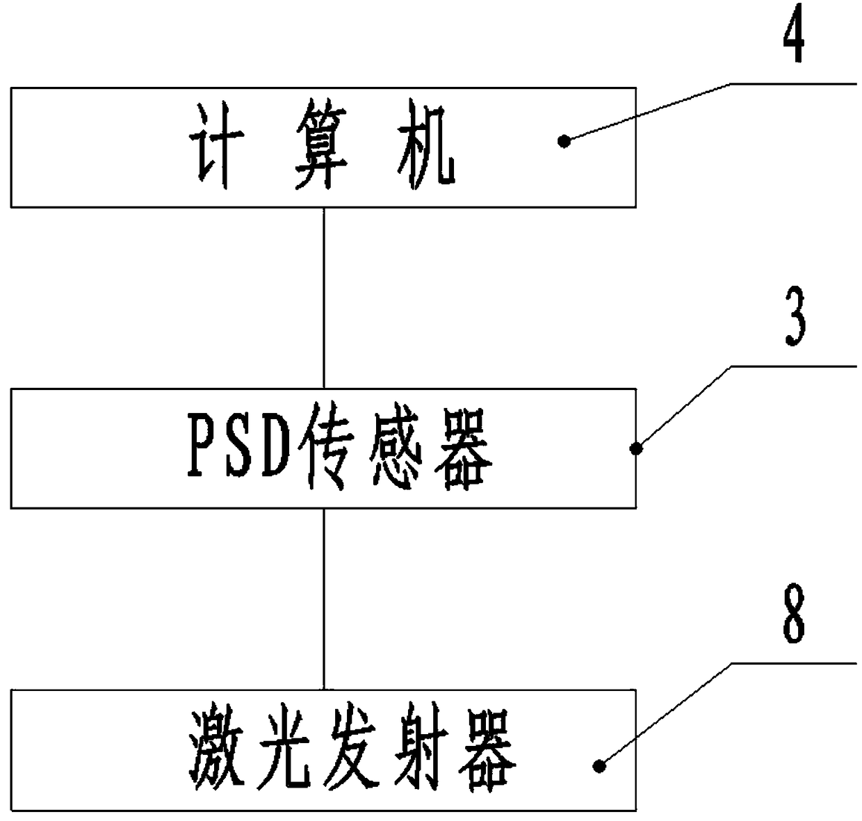
[0037] Step 2) PSD sensors 3 are set in each laser detection tube 2 of the cement concrete pipe 1 at the front end of the pipe jacking, and a computer 4 connected with the PSD sensor 3 is arranged outside the cement concrete pipe 1, and the computer 4 is arranged in the caisson, so as to facilitate Workers monitor the jacking direction of pipe jacking in real time;

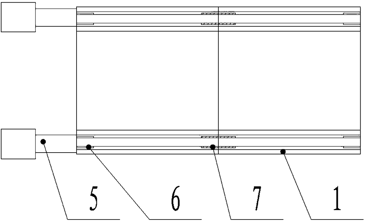
[0038] Step 3) Butt the cement concrete pipe 1 that will be pushed in later with the end of the cement concrete pipe that has been pushed in, and the laser detection tubes of the two connected cement concrete pipes are aligned front and back. When...

Embodiment 2

[0049] like Figure 1-3 As shown, an artificial pipe jacking control system of the present invention includes jacks and cement concrete pipes, and is characterized in that: there are two laser detection tubes symmetrically in the pipe wall of each cement concrete pipe; the cement concrete pipe at the front end of the pipe jacking Each laser detection tube is equipped with a PSD sensor, PSD (Position Sensitive detector) is a position sensitive detector. It is divided into two types of products: one-dimensional PSD and two-dimensional PSD. PSD is a PIN photodiode composed of one or two surfaces with uniform impedance. Compared with discrete element detectors, it has the advantages of high position resolution, simple reaction current, and fast (related to the position of the light spot).

[0050] A computer connected to the PSD sensor is provided outside the cement concrete pipe; the cement concrete pipe that is subsequently pushed in is docked with the end of the cement concret...


PUM


Abstract

The invention discloses a manual l jacking pipe control method and control system. Two laser detection pipes are symmetrically arranged in the wall of each cement concrete pipe, a PSD sensor is arranged at the position, on the front end of a jacking pipe, in each laser detection pipe of each cement concrete pipe, a computer connected with the PSD sensors are arranged outside each cement concrete pipe, and laser emitters are arranged at the position, on the outer end of the jacking pipe, in the laser detection pipes of one cement concrete pipe, laser emitted by the laser emitters is irradiatedon the PSD sensors to form light spots, the PSD sensors collect and record information of light spot position changes, and the computer analyzes collected data, the straightness error of the cement concrete pipes can be evaluated. Through manual adjusting of a jack, the jacking direction of the cement concrete pipes can be adjusted; in the manual jacking pipe construction process, the extension deviation of a pipeline underground can be corrected, the jacking direction is effectively controlled, a deviation correcting control system and a jacking device are integrated, safety is improved, thedifficulty of pipeline deviation correcting in the pipeline jacking process can be effectively reduced, and the comprehensive cost is reduced.

Description

technical field [0001] The invention relates to the technical field of artificial underground pipe jacking in municipal engineering construction, in particular to an artificial pipe jacking control method and control system. Background technique [0002] In urban road widening and reconstruction projects, the geology is relatively complex. During the construction, both the construction period and the closed traffic problem must be considered. If the construction is carried out according to the conventional construction method (grooving and sloping, slotting support), the safety of the surrounding buildings cannot be guaranteed. , At the same time, the construction cost is increased, and the construction period cannot be guaranteed. In addition, in the conventional construction method, certain trench support measures are required for slotting construction. Once the construction environment changes, the construction conditions are complicated, the construction period is long, ...

Claims


Application Information

Patent Timeline
IPC IPC(8): F16L1/028F16L1/06G01B11/27G01S19/14
CPCF16L1/028F16L1/06G01B11/27G01S19/14
Inventor 刘建国彭德坤
Owner CHINA MCC5 GROUP CORP
Why Eureka
Try Eureka