
Illuminating assembly applied to laser projection device and laser projection device

A technology for lighting components and laser projection, applied in the field of projection, can solve the problems of high cost and large volume of lighting components, and achieve the effects of increasing the refraction angle, reducing the lateral size, and shortening the lateral propagation distance.

Inactive Publication Date: 2018-08-28
QINGDAO HISENSE LASER DISPLAY CO LTD
View PDF6 Cites 5 Cited by
  • Summary
  • Abstract
  • Description
  • Claims
  • Application Information

AI Technical Summary

Problems solved by technology

[0005] The object of the present invention is to provide a lighting assembly used in a laser projection device, so as to solve the defects of large volume and high cost of the lighting assembly in the laser projection device proposed in the background art

Method used


Image

  • Illuminating assembly applied to laser projection device and laser projection device
  • Illuminating assembly applied to laser projection device and laser projection device
  • Illuminating assembly applied to laser projection device and laser projection device

Examples


Embodiment Construction

[0028] The following will clearly and completely describe the technical solutions in the embodiments of the present invention with reference to the accompanying drawings in the embodiments of the present invention. Obviously, the described embodiments are only part of the embodiments of the present invention, not all of them. Based on the embodiments of the present invention, all other embodiments obtained by persons of ordinary skill in the art without creative efforts fall within the protection scope of the present invention.

[0029] It should be noted that all directional indications (such as up, down, left, right, front, back...) in the embodiments of the present invention are only used to explain the relationship between the components in a certain posture (as shown in the figure). Relative positional relationship, movement conditions, etc., if the specific posture changes, the directional indication will also change accordingly.

[0030] In addition, in the present inve...


PUM


Abstract

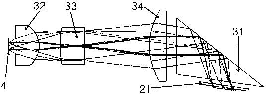
The invention provides an illuminating assembly applied to a laser projection device. The illuminating assembly comprises a first spherical lens, a second spherical lens, a non-spherical lens and a TIR prism which are sequentially arranged along a light path emergent from a light guide pipe to a light valve, wherein the incident surface of the first spherical lens is a concave surface, and the emergent surface of the first spherical lens is a convex surface; both the incident surface and the emergent surface of the second spherical lens are convex surfaces; the incident surface of the non-spherical lens is a convex surface; the diopter Phi 1 of the first spherical lens is positive and is greater than or equal to 17D and less than or equal to 56D; and the diopter Phi 2 of the second spherical lens is positive and is greater than or equal to 24.5D and less than or equal to 33.5D. The refraction angle of a light beam in an illuminating light path can be increased, the transverse propagation distance of the light path can be shortened, and the transverse size of the illuminating assembly can be greatly reduced.

Description

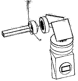
technical field [0001] The invention relates to the field of projection technology, in particular to an illumination assembly and a laser projection device applied to a laser projection device. Background technique [0002] A projection device is a device that can project images or videos onto a screen, and is widely used in homes, offices, schools, and entertainment venues. As an emerging projection display technology, laser projection products have higher brightness and lifespan than LED projection products. However, at present, laser projectors generally have the problems of large size and high price, which seriously affects the development of laser cinemas. [0003] Such as figure 1 , 2 As shown, it is a schematic structural diagram of the lighting components in the projection device used in the design of the lighting system in the prior art. The prior art generally adopts the architectural mode of 4 spherical lenses, 2 flat reflectors, and TIR, that is, 4 spherical ...

Claims


Application Information

Patent Timeline
Patent Type & Authority Applications(China)
IPC IPC(8): G03B21/20G02B19/00
CPCG03B21/2033G02B19/0028G02B19/0047G03B21/206G03B21/2066G03B21/208
Inventor 王宇
Owner QINGDAO HISENSE LASER DISPLAY CO LTD
Learn More