
Battery pack and battery case thereof

A box and battery technology, used in battery/battery traction, battery pack components, battery box/jacket, etc., can solve welding deformation and residual stress that cannot be completely eliminated, prone to defects and cracks, and reliable battery box It can save the internal space of the box, reduce the welding force, and avoid the welding failure.

Pending Publication Date: 2018-08-28
AIWAYS AUTOMOBILE CO LTD
View PDF0 Cites 20 Cited by
  • Summary
  • Abstract
  • Description
  • Claims
  • Application Information

AI Technical Summary

Problems solved by technology

However, there are many disadvantages in the case of the battery pack using profile tailor welding
For example, welding is prone to produce pores, defects and cracks, etc. Although some problems can be solved by using different welding processes, the welding deformation and residual stress generated during the welding process cannot be completely eliminated. At the same time, welding will cause material properties to decline, especially The welding of the corners around the box body has poor welding strength, and it is easy to fail when encountering large loads and long-term use
In addition, for different materials with large performance differences, it is difficult to weld
It can be seen that the reliability of the battery box in the prior art is low

Method used


Image

  • Battery pack and battery case thereof
  • Battery pack and battery case thereof
  • Battery pack and battery case thereof

Examples


Embodiment Construction

[0041] Example embodiments will now be described more fully with reference to the accompanying drawings. Example embodiments may, however, be embodied in many forms and should not be construed as limited to the embodiments set forth herein. Rather, these embodiments are provided so that this disclosure will be thorough and complete, and will fully convey the concept of the example embodiments to those skilled in the art. The same reference numerals denote the same or similar structures in the drawings, and thus their repeated descriptions will be omitted.

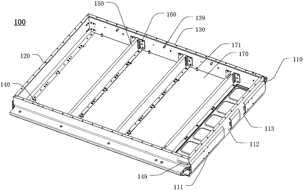
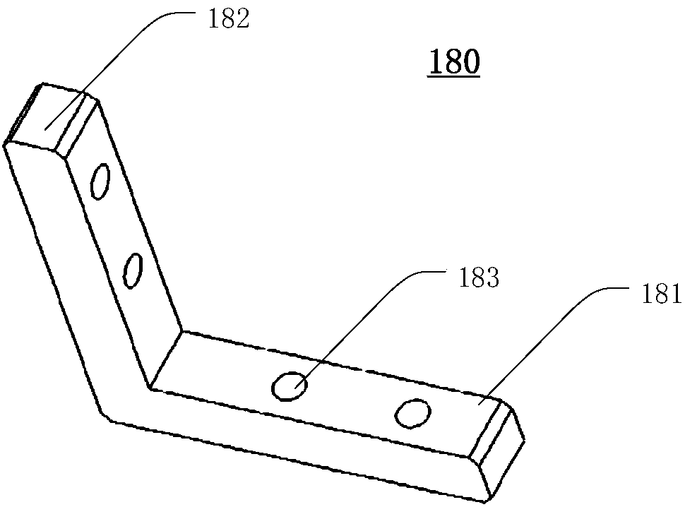
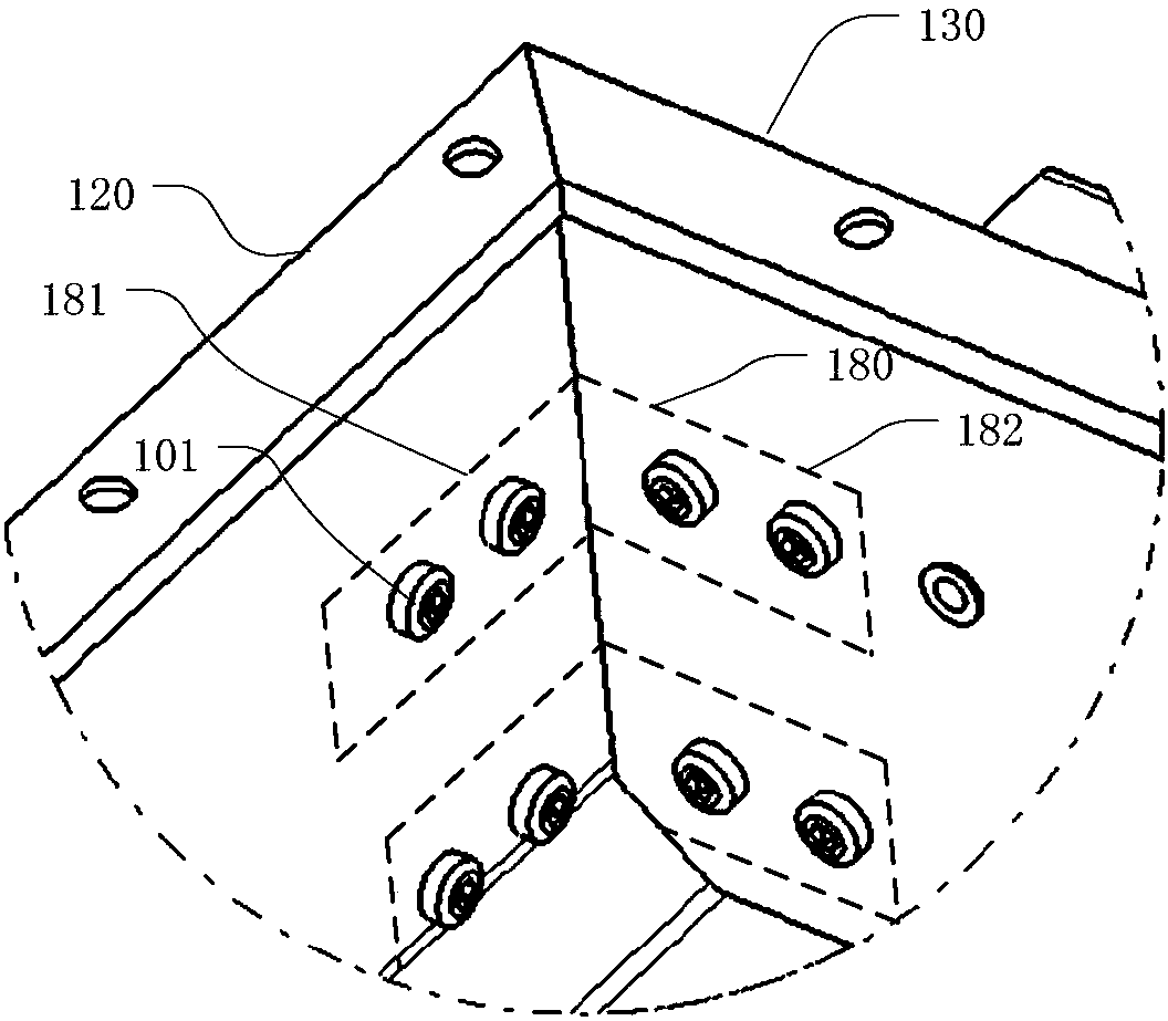
[0042] combine first Figure 1 to Figure 7 The battery case provided by the present invention will be described. figure 1 It is a perspective view of a battery case according to an embodiment of the present invention. figure 2 It is a schematic diagram of a corner connector according to an embodiment of the present invention. image 3 It is a schematic diagram of the connection between the first beam and the second bea...


PUM


Abstract

The invention provides a battery pack and a battery case thereof. The battery case comprises a bottom plate, a plurality of first beams, a plurality of second beams, a plurality of corner connectors,aplurality of fixed beams, and a plurality of fixed beam connectors, wherein the first and second beams are fixed on the bottom plate to form an accommodating cavity, each first beam is provided witha first cavity, and each second beam is provided with a second cavity; each corner connector is provided with a first connecting portion and a second connecting portion, which form a first angle, thefirst connecting portion of each corner connector islocated in the first cavity of the corresponding first beam and fixedly connected to the first beam, the second connecting portion of each corner connector is located in the second cavity of the corresponding second beam and is fixedly connected to the second beam; the fixed beams are fixed on the bottom plate and are located in the accommodatingcavities., and two ends of each fixed beam are connected with the second beams, respectively; each of the fixed beam connectors is connected with a fixed beam and a second beam. The reliability of the battery case provided by the invention is improved.

Description

technical field [0001] The invention relates to an electric vehicle, in particular to a battery pack and a battery case thereof. Background technique [0002] An existing battery case adopts sheet metal and stamping technology, which is relatively low in cost but heavy in weight, and cannot realize the lightweight of the battery pack and the whole vehicle. In order to solve the problem of light weight, another existing battery box usually adopts profile tailor welding. However, there are many disadvantages in using profile tailor welding for the box body of the battery pack. For example, welding is prone to produce pores, defects and cracks, etc. Although some problems can be solved by using different welding processes, the welding deformation and residual stress generated during the welding process cannot be completely eliminated. At the same time, welding will cause material properties to decline, especially The welding of the corners around the box has poor welding stre...

Claims


Application Information

Patent Timeline
Patent Type & Authority Applications(China)
IPC IPC(8): H01M2/10H01M2/08B60L11/18H01M50/24H01M50/244
CPCB60L50/64H01M50/183H01M50/20Y02T10/70Y02E60/10
Inventor 邱福生
Owner AIWAYS AUTOMOBILE CO LTD
Learn More