
Electronic circuit board mounting and fixing apparatus

A technology for electronic circuit boards and fixing devices, applied in the direction of support structure installation, clamping/extracting devices, etc., can solve the problems of batch installation and fixing of unfavorable circuit boards, inconvenient installation and disassembly, burnt circuit boards, etc., and achieve good fixing effect , The installation and removal steps are simple, and the effect of avoiding circuit damage

Inactive Publication Date: 2018-08-28
桂林恒正科技有限公司
View PDF0 Cites 6 Cited by
  • Summary
  • Abstract
  • Description
  • Claims
  • Application Information

AI Technical Summary

Problems solved by technology

[0003] Nowadays, when the circuit board is used, the circuit board is loose due to long-term work and cannot work normally, and the loose circuit board works for a long time to cause poor contact, which may easily cause the circuit board to be burned and affect the work. Therefore, when using the circuit board, it is necessary to replace the It is fixed to increase the service life of the circuit board. However, the existing circuit board fixing devices are all fixed by screws at the four corners of the circuit board. The batch installation and fixing of circuit boards, therefore, a kind of electronic circuit board installation and fixing device is proposed in view of the above problems

Method used


Image

  • Electronic circuit board mounting and fixing apparatus
  • Electronic circuit board mounting and fixing apparatus
  • Electronic circuit board mounting and fixing apparatus

Examples


Embodiment Construction

[0021] The technical solutions in the embodiments of the present invention will be clearly and completely described below in conjunction with the accompanying drawings in the embodiments of the present invention. Obviously, the described embodiments are only a part of the embodiments of the present invention, rather than all the embodiments. Based on the embodiments of the present invention, all other embodiments obtained by those of ordinary skill in the art without creative work shall fall within the protection scope of the present invention.

[0022] See Figure 1-5 , The present invention provides a technical solution:

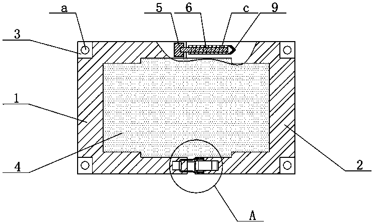
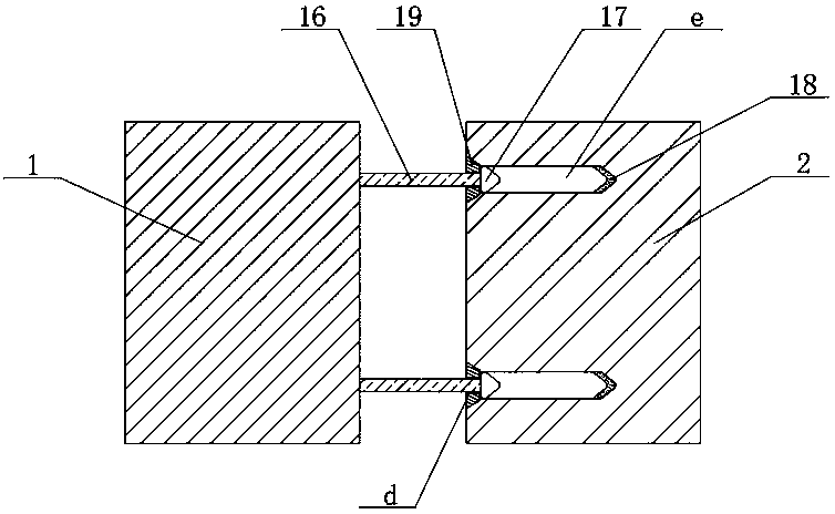
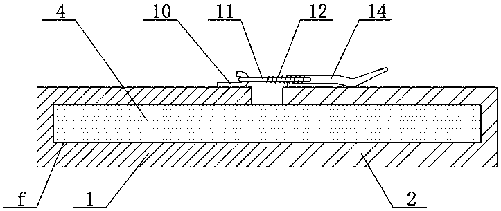
[0023] An electronic circuit board mounting and fixing device includes a left fixing plate 1, a right fixing plate 2 and a circuit board 4. The upper and lower ends of the left fixing plate 1 and the right fixing plate 2 are fixedly connected with fixing pieces 3, and the fixing pieces 3 A mounting hole a is opened in the center, a bar 16 is fixedly connected ...


PUM


Abstract

The invention relates to the technical field of circuit equipment, particularly an electronic circuit board mounting and fixing apparatus. The electronic circuit board mounting and fixing apparatus comprises a left fixed board, a right fixed board and a circuit board; a fixed base groove is formed in the top end side edge of the left fixed board; a fixed base is arranged in the fixed base groove;the center of the right end of the fixed base is fixedly connected with a sliding rod; the right end of the sliding rod passes through the left fixed board to be fixedly connected with the right fixedboard; a horizontal first sliding groove is formed in the top end side edge of the right fixed board; a rubber base is arranged at the bottom end of the first sliding groove; the right end of the sliding rod is fixedly connected with a piston head and glidingly connected with the first sliding groove; the left side, on the outer side of the sliding rod, of the piston head is sleeved with a compression spring; the other side of the top end of the left fixed board is fixedly connected with a hook; the other side of the top end of the right fixed board is rotationally connected with a rotary shaft; and the right end of the rotary shaft is fixedly connected with a spanner. The electronic circuit board mounting and fixing apparatus has the advantages of simple mounting and fixing, conveniencein detachment, and wide market demand and is worthy of popularization.

Description

Technical field [0001] The invention relates to the technical field of electronic equipment, in particular to an electronic circuit board mounting and fixing device. Background technique [0002] The names of the circuit boards are: ceramic circuit boards, alumina ceramic circuit boards, aluminum nitride ceramic circuit boards, circuit boards, PCB boards, aluminum substrates, high frequency boards, thick copper boards, impedance boards, PCBs, ultra-thin circuit boards, ultra Thin circuit boards, printed (copper etching technology) circuit boards, etc., circuit boards make circuits miniaturized and intuitive, and play an important role in the mass production of fixed circuits and optimizing the layout of electrical appliances. Circuit boards are the most active in the contemporary electronic component industry. The industry’s growth rate is generally about 3 percentage points higher than that of the electronic component industry. From the perspective of development, China’s circui...

Claims


Application Information

Patent Timeline
Patent Type & Authority Applications(China)
IPC IPC(8): H05K7/14
CPCH05K7/1405H05K7/1409
Inventor 李名辉
Owner 桂林恒正科技有限公司
Learn More