[0021] The specific embodiments of the present invention will be described in further detail below with reference to the accompanying drawings and embodiments. The following examples are intended to illustrate the present invention, but not to limit the scope of the present invention.
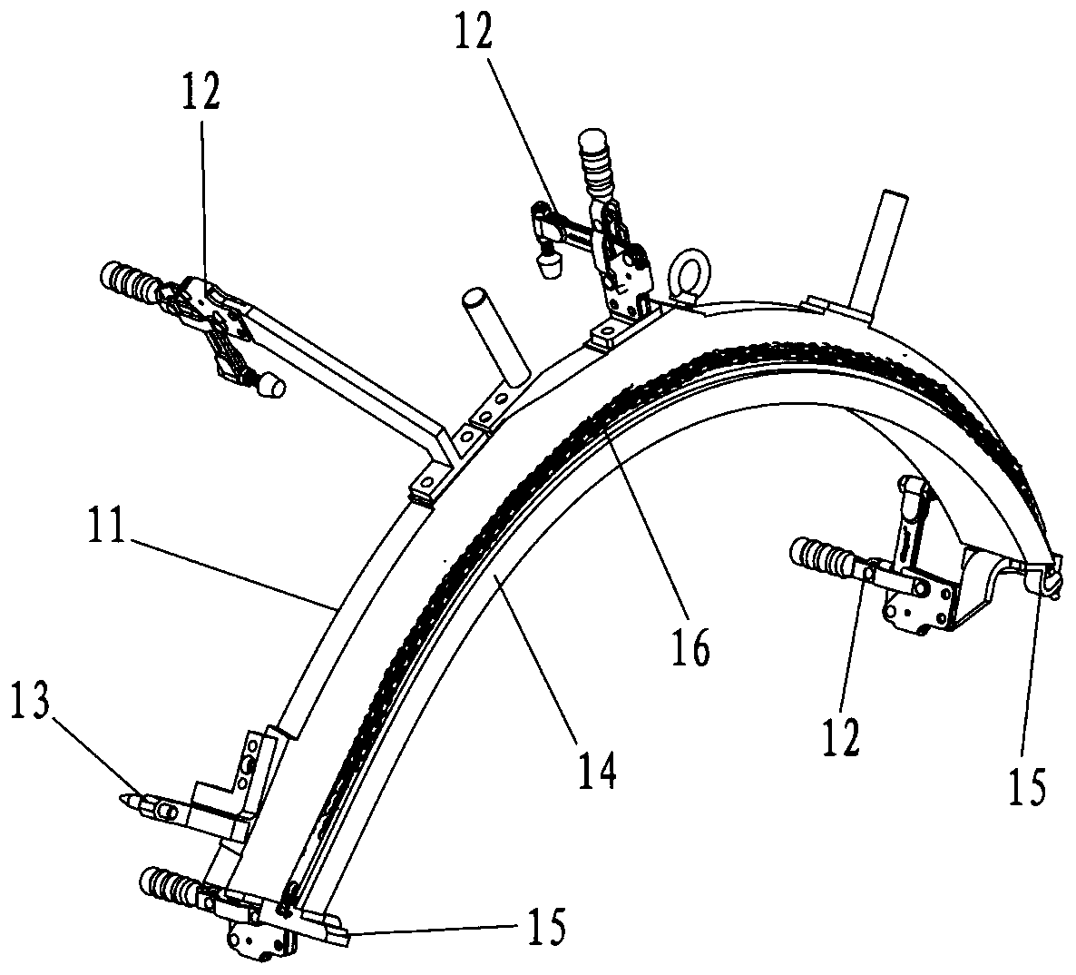
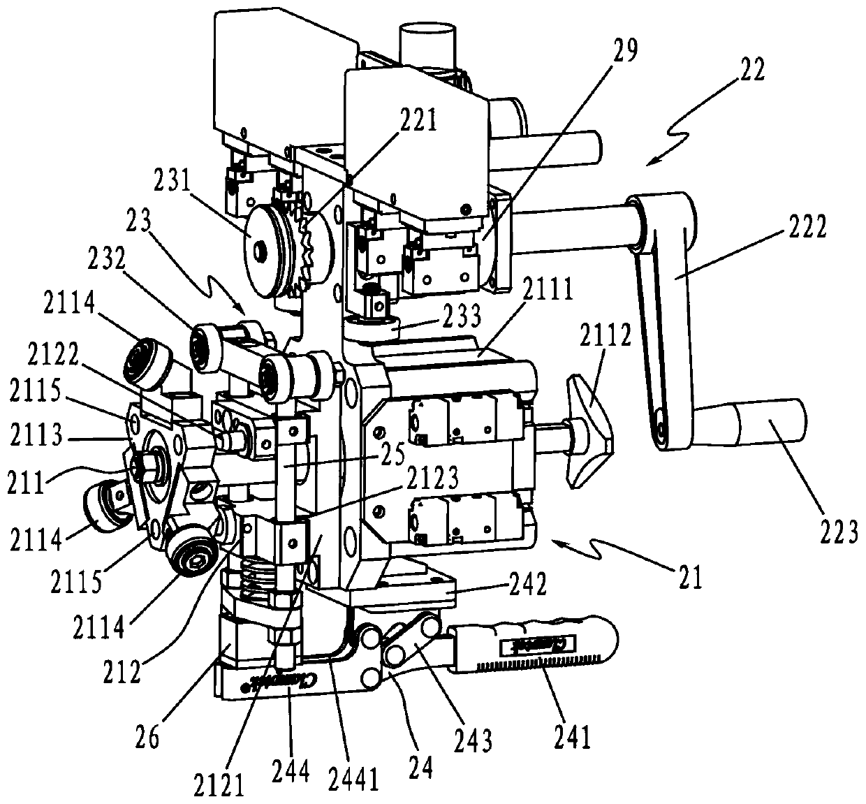
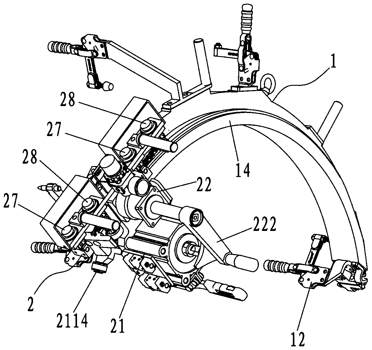
[0022] combine Figure 1 to Figure 4 As shown, an automobile wheel cover hemming device according to an embodiment of the present invention is schematically shown, which includes a tire membrane 1 and a hemming machine 2, wherein the tire membrane 1 includes a tire membrane body 11, and the tire membrane body 11 is provided with Several clamps 12 and positioning pins 13, through which the tire membrane 1 can be quickly and accurately fixed to the side wall of the vehicle body. The cross-section of the tire membrane 1 is "L" shaped, and a traction member 16 is provided along the hemming track 14, and limit stops 15 are also provided at both ends of the hemming track 14, which are used to limit the hemming machine 2 in the wrapping. The stroke during reciprocating movement on the side rail 14 ; the tire membrane 1 can be designed according to the size of the specific wheel cover of different models, and the traction member 16 changes with the shape of the side rail 14 .
[0023] Please refer to figure 2 As shown, the hemming machine 2 includes a frame, a hemming mechanism 21 arranged on the frame, a driving mechanism 22 and a guiding and positioning mechanism 23; wherein, the hemming mechanism 21 and the driving mechanism 22 are arranged side by side, and the driving mechanism 22 is located in the bag On the upper part of the hemming mechanism 21, the guiding and positioning mechanism 23 is located on the left side of the hemming mechanism 21 and the driving mechanism 22, such a layout makes the entire mechanism of the hemming machine 2 more compact;
[0024] The hemming mechanism 21 includes a hemming assembly 211 and a locking assembly 212. The hemming assembly 211 is provided with an actuator 2111, a station switching member 2112, and a number of rollers 2114 arranged around the axis of the output shaft of the actuator 2111, and the station is switched. The component 2112 is coaxially connected to the output shaft of the actuator 2111; specifically, the station switching component 2112 is arranged on the right end of the actuator 2111, and the hemming assembly 211 is also provided with a roller mounting plate 2113, which is mounted on the working position. On the output shaft at the left end of the actuator 2111, a plurality of rollers 2114 are mounted on the roller mounting plate 2113 through the roller mounting shaft, and the respective axis of each roller 2114 is at a different angle from the axis of the output shaft of the actuator 2111, so as to satisfy the Multi-process and different angle hemming work can be completed on the same hemming machine, which saves the development and maintenance costs of the equipment;
[0025] Please refer to figure 2 As shown, the hemming assembly 211 has a hemming station. When the station switching member 2112 is rotated to drive one of the rollers 2114 to move to the hemming station, the actuator 2111 acts so that the locking assembly 212 will be in the hemming station. The position of the roller 2114 is locked; specifically, the locking assembly 212 includes a fixed seat 2121 connected to the left end of the actuator 2111 and a plurality of locking pins 2122 installed on the fixed seat 2121. The roller mounting plate 2113 is provided with a plurality of The lock pin 2122 corresponds to the lock hole 2115. The actuator 2111 can drive the roller mounting plate 2113 to reciprocate left and right, so that the lock hole 2115 is sleeved on the lock pin 2122 and disengaged from the lock pin 2122. When the actuator 2111 drives the roller mounting plate When the 2113 moves to the left and retracts, so that the lock hole 2115 is sleeved on the lock pin 2122, the station switching member 2112 cannot rotate the roller mounting plate 2113 to switch the position of the roller 2114. At this time, the position of the roller 2114 is locked. When the actuator 2111 drives the roller mounting plate 2113 to move to the right, when the lock hole 2115 is released from the lock pin, the roller mounting plate 2113 is in an unlocked state. 2114 location.
[0026] Please continue to combine Figure 1 to Figure 4 As shown, the hemming machine 2 is positioned and installed on the hemming track 14 through the guiding and positioning mechanism 23 , the driving member 221 of the driving mechanism 22 is connected with the traction member 16 , and the action of the driving member 221 drives the hemming machine 2 to reciprocate along the hemming track 14 movement, so that the roller 2114 in the hemming station can synchronously complete the hemming work; specifically, please refer to figure 2 As shown, the driving mechanism 22 also includes a "Z"-shaped rocker 222, one end of the "Z"-shaped rocker is a holding end 223, and the driving member 221 is a sprocket mounted on the other end of the "Z"-shaped rocker 222 , the traction member 16 is a chain, and the sprocket is engaged with the chain. The worker can hold the grip end 223 of the "Z"-shaped rocker to shake the "Z"-shaped rocker 222, thereby driving the traction member 16 (sprocket) to rotate, Since the sprocket is engaged with the chain, and the chain is fixed, the sprocket moves along the chain, so as to achieve the purpose of driving the hemming machine 2 to reciprocate along the hemming track 14 by the driving member 221, so that the hemming station The rollers 2114 complete the hemming work synchronously; preferably, a reducer 29 can be set on the other end of the "Z"-shaped rocker 222, and the traction member 16 is installed on the output shaft of the reducer 29, so that the worker can shake the "Z" ” shaped rocker 222 is more labor-saving to reduce the labor intensity of workers.
[0027] Please continue to refer to figure 2 As shown, the hemming machine 2 is positioned and installed on the hemming track 14 of the tire membrane 1 through the guide wheel positioning mechanism 23, that is, the guide positioning mechanism 23 includes an upper guide wheel group 231, a lower guide wheel group 232 and a set of upper guide wheels 232. The lateral guide wheel group 233 on the right side between the guide wheel group 231 and the lower guide wheel group 232 is provided with a clamping member 24 on the lower guide wheel group 232, and the upper guide wheel group 231 and the driving member 221 are arranged coaxially; The gap between the wheel set 231 and the lower guide wheel set 232 constitutes a clamping space, and the hemming rail 14 is located in the clamping space, and the right end face of the hemming rail 14 is in contact with the lateral guide wheel set 233, and the lateral guide wheel The group 233 can limit the hemming machine 2 laterally; the clamping member 24 has a clamping position and a loosening position. When the clamping member 24 is switched from the loosening position to the clamping position, the clamping member 24 drives the lower guide wheel group 232 Moving up, the hemming rail 14 is clamped, and when the clamping member 24 is switched from the clamping position to the releasing position, the clamping member 24 drives the lower guide wheel group 232 to move down to release the hemming rail 14 .
[0028] When the clamping member 24 is switched from the loosening position to the clamping position, the clamping member 24 drives the lower guide wheel group 232 to move up, and when the hemming rail 14 is clamped, the upper guide wheel group 231 and the lower guide wheel group 232 are matched to each other. The hemming machine 2 is limited in the upper and lower directions, and the lateral guide wheel group 233 cooperates with the engagement of the sprocket and the chain to limit the hemming machine 2 laterally (left and right lateral directions), so that the hemming machine 2 can only be The hemming track 14 moves back and forth, thereby improving the hemming accuracy of the hemming machine 2;
[0029] When the clamping member 24 is switched from the clamping position to the releasing position, the clamping member 24 drives the lower guide wheel group 232 to move down, and when the hemming rail 14 is released, the hemming machine 2 is removed from the hemming rail of the tire membrane 1 . 14 and remove it.
[0030] Please continue to refer to figure 2 As shown, the clamping member 24 drives the lower guide wheel assembly 232 to move up and down to achieve clamping and releasing the hemming rail 14 , that is, the clamping member 24 includes a handle 241 , a mounting seat 242 , a connecting rod 243 and a pressing rod 244 , the clamping member 24 is installed on the bottom of the frame through the mounting seat 242, the handle 241, the mounting seat 242, the pressure rod 244 and the connecting rod 243 are sequentially connected to form a four-link structure, and the lower guide wheel group 232 is connected to the swing of the pressure rod 244. On the end, according to the motion principle of the four-bar linkage structure, when the handle is moved upward, the swinging end of the pressing rod 244 can be driven to move upward simultaneously, and the four-bar linkage structure is self-locked. Since the lower guide wheel group 232 is connected to the pressing rod 244 on the swinging end, so that the lower guide wheel group 232 moves synchronously on the ground and clamps the hemming rail 14. Similarly, when the handle is turned downward, the lower guide wheel group 232 can move synchronously underground to loosen the hemming rail. 14.
[0031] Preferably, the lower guide wheel set 232 is connected to the swinging end of the pressing rod 244 through the guide rod 25 , the fixing seat 2121 of the locking assembly 212 is provided with a guide hole 2123 , the guide rod 25 movably passes through the guide hole 2123 , and the guide rod 25 One end of the guide rod 25 is fixedly connected with the lower guide wheel group 232, and the other end of the guide rod 25 is movably connected with the swinging end of the pressure rod 244;
[0032] Specifically, the guide rod 25 is connected with the swinging end of the pressing rod 244 through the connecting seat 26, the swinging end of the pressing rod 244 is provided with a guide groove 2441, the connecting seat 26 is provided with a slider, and the slider is movably clamped in the guide groove 2441, so as to avoid positional interference between the up and down movement of the guide rod 25 when the swinging end of the pressing rod 244 swings up and down.
[0033] Please refer to image 3 As shown, the frame is also provided with an open button 27 for controlling the extension of the output shaft of the actuator 2111, and a clamping button 28 for controlling the retraction of the output shaft of the actuator 2111, wherein the open button 27 is set to Two, it is necessary to press the two open buttons 27 at the same time to control the output shaft of the actuator 2111 to extend, which can ensure the safety of use and avoid accidents caused by accidental pressing; The output shaft of the actuator 2111 can be controlled to retract by pressing the two clamping buttons 28 at the same time, which can ensure the safety of use and avoid accidents caused by mistaken pressing.
[0034] In a preferred embodiment of the present invention, the number of rollers 2114 is three, and the three rollers are distributed in a regular triangle around the axis of the output shaft of the actuator 2111 . The included angles of the axes are 30°, 60° and 90°, respectively.
[0035] The following is an example of the roller 2114 with three axes and the axis of the output shaft of the actuator 2111 having three angles of 30°, 60° and 90° as an example to illustrate the automobile wheel cover according to the embodiment of the present invention. The working principle of the hemming device: First, the tire membrane 1 will be quickly and accurately fixed to the side panel of the vehicle body through the clamp 12 and the positioning pin 13, and then the upper guide wheel group 231 and the lower guide wheel group 231 of the guiding and positioning mechanism 23 of the hemming machine 2 will be guided. The clamping space formed by the guide wheel group 232 is engaged with the edge covering track 14 of the tire membrane 1, and at the same time, the driving member 221 (sprocket) is engaged with the traction member 16 (rack), and the handle 241 is moved upward to make the lower guide wheel The group 232 moves up and clamps the hemming rail 14, thereby completing the process of installing the hemming machine 2 on the tire membrane;
[0036] Next, turn the station switching member 2112, rotate the roller with an included angle of 30° to the hemming station, press the clamping button 28, so that the actuator 2111 drives the roller mounting plate 2113 to move and retract to the left, so that the lock The hole 2115 is sleeved on the lock pin 2122 to lock the position of the roller mounting plate 2113, and then the "Z" shaped rocker 222 is shaken, so that the driver 221 drives the hemming machine 2 to move from the front end of the hemming rail 14 to the hemming rail. 14, so that the rollers with an included angle of 30° can synchronously complete the hemming work, and then press the open button 27, the actuator 2111 drives the roller mounting plate 2113 to move to the right, so that the lock hole 2115 is released from the lock pin When the roller mounting plate 2113 is unlocked, the station switching member 2112 is rotated again, the roller with an included angle of 60° is rotated to the hemming station, and the clamping button 28 is pressed, so that the actuator 2111 drives the roller mounting plate 2113 to the hemming station. Move to the left and retract, so that the lock hole 2115 is sleeved on the lock pin 2122, the position of the roller mounting plate 2113 is locked, and then the "Z" shaped rocker 222 is shaken, so that the driver 221 drives the hemming machine 2 from the hemming track. The rear end of 14 returns to the front end of the hemming track 14, so that the rollers with an included angle of 60° complete the hemming work synchronously. Finally, press the open button 27, and the actuator 2111 drives the roller mounting plate 2113 to move to the right and extend , when the lock hole 2115 is released from the lock pin, unlock the roller mounting plate 2113, turn the station switching member 2112 again, rotate the roller with an included angle of 90° to the hemming station, and press the clamping button 28 to activate the The device 2111 drives the roller mounting plate 2113 to move and retract to the left, so that the lock hole 2115 is sleeved on the lock pin 2122, and the position of the roller mounting plate 2113 is locked, and then the "Z" shaped rocker 222 is shaken, so that the driving member 221 drives the The hemming machine 2 goes from the front end of the hemming track 14 to the rear end of the hemming track 14, so that the rollers with an included angle of 90° can complete the hemming work synchronously, so that the same hemming machine can complete 30°, 60° ° and 90 ° three-angle hemming work.
[0037] To sum up, in the hemming device of the automobile wheel cover according to the embodiment of the present invention, the tire membrane 1 can be quickly fixed on the side wall of the vehicle body by the clamp 12 and the positioning pin 13, and the hemming machine 2 can be positioned by the guiding and positioning mechanism 23. Installed on the hemming track 14 of the tire membrane 1, the roller 2114 that matches the process is rotated to the hemming station through the station switching member 2112, and the position of the roller is locked by the locking assembly 212. The driving member 221 is connected with the traction member 16, and the action of the driving member 221 drives the hemming machine 2 to move along the hemming track 14, so that the rollers in the hemming station can complete the hemming work in the same steps. , During the reciprocating motion of the hemming machine 2 along the hemming track, multiple hemming processes of different angles are completed. The entire hemming process is simple to operate, which greatly improves the hemming efficiency of manual hemming, and realizes the same The hemming process of different angles is completed on one hemming machine, which saves the development and maintenance costs of the equipment.
[0038] The above are only the preferred embodiments of the present invention. It should be pointed out that for those skilled in the art, without departing from the technical principle of the present invention, several improvements and substitutions can be made. These improvements and substitutions It should also be regarded as the protection scope of the present invention.